[Guide] DC-DC Charger (for leisure battery) -- How I Done It --

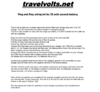
the @travelvolts kit give you a white and red cable.

one will be starter battery, one will be leisure battery.

Connect the Red fused wire to the input terminal of your charger. On CTEK this is marked with A + in. On Redarc this will be the Red wire. On Ablemail and Victron this will be Input.

For other chargers consult manufacturers hand book.

Connect the White un-fused wire to the leisure battery or output connection on your charger. On CTEK this is marked with a battery symbol and the word OUT. On Redarc this is the brown wire. On Ablemail this is OUT.

Connect the supplied loose brown wire to the negative, ground or 0V connection on your charger and the other end to the negative terminal of the leisure battery. The thin red wire on the new loom is the ignition control wire and simply connects to the thin red wire on the CTEK, or, for Redarc connect it to the thin blue. On Ablemail connecto to “sense terminal”. On Victron connect to 2 High.


1618770755344.png
 
the @travelvolts kit give you a white and red cable.

one will be starter battery, one will be leisure battery.

Connect the Red fused wire to the input terminal of your charger. On CTEK this is marked with A + in. On Redarc this will be the Red wire. On Ablemail and Victron this will be Input.

For other chargers consult manufacturers hand book.

Connect the White un-fused wire to the leisure battery or output connection on your charger. On CTEK this is marked with a battery symbol and the word OUT. On Redarc this is the brown wire. On Ablemail this is OUT.

Connect the supplied loose brown wire to the negative, ground or 0V connection on your charger and the other end to the negative terminal of the leisure battery. The thin red wire on the new loom is the ignition control wire and simply connects to the thin red wire on the CTEK, or, for Redarc connect it to the thin blue. On Ablemail connecto to “sense terminal”. On Victron connect to 2 High.


View attachment 112977
That's what I've done - although there is no white wire, it is now a black one with a white mark on it. I'm beginning to wonder if the relay could be plugged in upside down or something!
 
Thanks for replying.
"disconnect your leisure battery by removing the earth" - you mean remove the clamp from the negative terminal of the leisure battery?
"Then test for 12V at the two points on the CTEK where the batteries connect" - I do have a multimeter but no idea how to use it!
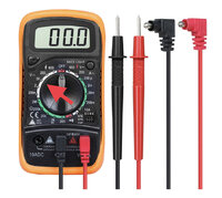
OK. You need to set the multimeter to DC volts and to 20V to measure 12v. It will be something like the picture below and you should set it as shown with the arrow. You can see the V sign with the Dash with dots under it above the red arrow. That is the symbol for DC volts if your meter is slightly different Set it to where that symbol is.
If the meter has three sockets for the probes, connect the two where it shows for measuring Volts. In the picture below it is the centre and the one on the right and you can just see the markings for V and Ohms partially hidden by the red cable.
Then before you do anything else test the meter is correctly set by putting the probes across the battery terminals. If it is in the correct position it will read 12V or thereabouts. If you connect it in reverse it won’t matter, it will just show -12v.

You could then test for 12V at the two battery points on the CTEK. Touch the black probe to an earth point (or the -VE on the CTEK) and the red probe to A on the CTEK and you should see 12V. Do the same with the red probe on BATT on the CTEK and again you should have 12V.

Disconnect the leisure battery earth connection by removing the earth clamp on the battery.
Then repeat the two tests above on the CTEK. You should find you have 12V on either A or BATT but not both (as you have disconnected one of them).
If you have 12V at A but not at BATT, everything is connected correctly. Just reconnect the leisure battery as it was.
If you have 12V at BATT but not A, the two cables are connected the wrong way round. If this is the case, the quickest solution is to swap the two cables at the CTEK end. Before doing so, I’d unplug the cable loom from the socket (where the relay was previously) so you are not working on live cables.
If you do have to swap it round, once you’ve done so, repeat the test with the meter to confirm it is right, reconnect the leisure battery earth and then see how the CTEK performs. If you connect a mains charger to the starter battery the CTEK should kick in and charge the leisure, A and BATT LEDs will light up. Or, just turn the IGN on and it should do the same after a few seconds.

962A89D5-457A-4419-BBEF-95A8A39C1F1E.jpeg
 
OK. You need to set the multimeter to DC volts and to 20V to measure 12v. It will be something like the picture below and you should set it as shown with the arrow. You can see the V sign with the Dash with dots under it above the red arrow. That is the symbol for DC volts if your meter is slightly different Set it to where that symbol is.
If the meter has three sockets for the probes, connect the two where it shows for measuring Volts. In the picture below it is the centre and the one on the right and you can just see the markings for V and Ohms partially hidden by the red cable.
Then before you do anything else test the meter is correctly set by putting the probes across the battery terminals. If it is in the correct position it will read 12V or thereabouts. If you connect it in reverse it won’t matter, it will just show -12v.

You could then test for 12V at the two battery points on the CTEK. Touch the black probe to an earth point (or the -VE on the CTEK) and the red probe to A on the CTEK and you should see 12V. Do the same with the red probe on BATT on the CTEK and again you should have 12V.

Disconnect the leisure battery earth connection by removing the earth clamp on the battery.
Then repeat the two tests above on the CTEK. You should find you have 12V on either A or BATT but not both (as you have disconnected one of them).
If you have 12V at A but not at BATT, everything is connected correctly. Just reconnect the leisure battery as it was.
If you have 12V at BATT but not A, the two cables are connected the wrong way round. If this is the case, the quickest solution is to swap the two cables at the CTEK end. Before doing so, I’d unplug the cable loom from the socket (where the relay was previously) so you are not working on live cables.
If you do have to swap it round, once you’ve done so, repeat the test with the meter to confirm it is right, reconnect the leisure battery earth and then see how the CTEK performs. If you connect a mains charger to the starter battery the CTEK should kick in and charge the leisure, A and BATT LEDs will light up. Or, just turn the IGN on and it should do the same after a few seconds.

View attachment 112994
That's magic, thanks. I will do that next.
 
OK. You need to set the multimeter to DC volts and to 20V to measure 12v. It will be something like the picture below and you should set it as shown with the arrow. You can see the V sign with the Dash with dots under it above the red arrow. That is the symbol for DC volts if your meter is slightly different Set it to where that symbol is.
If the meter has three sockets for the probes, connect the two where it shows for measuring Volts. In the picture below it is the centre and the one on the right and you can just see the markings for V and Ohms partially hidden by the red cable.
Then before you do anything else test the meter is correctly set by putting the probes across the battery terminals. If it is in the correct position it will read 12V or thereabouts. If you connect it in reverse it won’t matter, it will just show -12v.

You could then test for 12V at the two battery points on the CTEK. Touch the black probe to an earth point (or the -VE on the CTEK) and the red probe to A on the CTEK and you should see 12V. Do the same with the red probe on BATT on the CTEK and again you should have 12V.

Disconnect the leisure battery earth connection by removing the earth clamp on the battery.
Then repeat the two tests above on the CTEK. You should find you have 12V on either A or BATT but not both (as you have disconnected one of them).
If you have 12V at A but not at BATT, everything is connected correctly. Just reconnect the leisure battery as it was.
If you have 12V at BATT but not A, the two cables are connected the wrong way round. If this is the case, the quickest solution is to swap the two cables at the CTEK end. Before doing so, I’d unplug the cable loom from the socket (where the relay was previously) so you are not working on live cables.
If you do have to swap it round, once you’ve done so, repeat the test with the meter to confirm it is right, reconnect the leisure battery earth and then see how the CTEK performs. If you connect a mains charger to the starter battery the CTEK should kick in and charge the leisure, A and BATT LEDs will light up. Or, just turn the IGN on and it should do the same after a few seconds.

View attachment 112994
Measured across leisure terminals, and got 12.4V. Measured at CTEK and A was 12.4V and Batt was 12.3V. Disconnected starter battery (easier to get to, measured at CTEK and A was 12.4, Batt was 1.1V...
I have reconnected starter. I pulled the relay plug and double-checked, it is only possible to connect this in one way, so no scope for user error there.
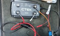
So I'm a bit stumped now. Here's a photo of how the CTEK is wired. Out is the black sheathed cable with inline fuse. A is the red cable. Negative is the brown cable connected to leisure negative.
20210419_075312.jpg
 
"Connect the Red fused wire to the input terminal of your charger. On CTEK this is marked with A + in. ......

Connect the White un-fused wire to the leisure battery or output connection on your charger. On CTEK this is marked with a battery symbol and the word OUT. "

It seems that the colour coding on Martyn's kit may have changed, or is back to front on the one I have received. The black sheathed cable is the one which is fused, the red cable is unfused. I have texted Martyn to double-check.
 
A in = starter battery POS

Batt symbol / out = leisure battery POS
 
Measured across leisure terminals, and got 12.4V. Measured at CTEK and A was 12.4V and Batt was 12.3V. Disconnected starter battery (easier to get to, measured at CTEK and A was 12.4, Batt was 1.1V...
I have reconnected starter. I pulled the relay plug and double-checked, it is only possible to connect this in one way, so no scope for user error there.
So I'm a bit stumped now. Here's a photo of how the CTEK is wired. Out is the black sheathed cable with inline fuse. A is the red cable. Negative is the brown cable connected to leisure negative.
View attachment 113017
It is connected the wrong way round. The testing you did shows that with the starter battery disconnected you had no voltage at BATT (out). What you should see with the starter disconnected is no voltage at A.
In addition, the instructions say you should connect the fused cable to A. The fuse is in the little black box which is connected to the cable with the black braiding on it. This is connected to BATT and should be connected to A.
Swap the two cables round and you should be good.
Swapped over, and at least charging the starter from mains charger now looks normal. Thanks for your help guys!
 
NEW 2021 - RENOGY

10% OFF Renogy Kit -


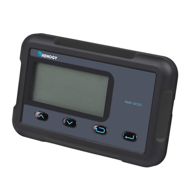
MONITORING SCREEN FOR DC-DC MPPT BATTERY CHARGER SERIES


1623451234219.png


DESCRIPTION​

The RMS-DCDC is a high precision meter designed for DC-DC MPPT Series onboard battery chargers. Engineered for an aesthetically clean and professional look once mounted, this meter can be flush-mounted and features a backlit LCD. Utilize the 4-key input to navigate through the LCD for system information, configure charging parameters, as well as identify any error codes. The RMS-DCDC is the perfect companion, offering operator feedback on your 2-battery system and keeping you up to date with important system information.

【First edition of the monitoring screen for the DC to DC battery charger with MPPT series, is not an ideal item for your setup if the auxiliary battery is lithium or if your vehicle comes with a smart alternator, you won't be able to check complete data of the charging data of the DC to DC batteries with MPPT,

The second edition will be released by the end of June, if this version is not suitable for your setup, please patiently wait for the updated version or get a BT2 module to monitor the charging data of your DC to DC battery charger with MPPT , thank you!】

If you have any questions regarding this product, please submit a case.

KEY FEATURES​

• Dual Battery Monitoring
  • Stay informed about your house and auxiliary battery's charging status and easily monitor the solar system's overall health.
• Adjustable Parameters
  • Program your charger settings, volts, and amps directly through the monitoring screen.
• Plug and Play
  • Simply connect an RJ45 directly to your DC-DC and let the screen take care of the rest.
• Accurate Readings
  • Precise tracking and monitoring ensure the latest real-time solar and alternator charging information.
Compatible Models: RBC50D1S RBC30D1S
 
I've had this unit since summer 2020 . . . but with all the Solar stuff doing the rounds i forgot about it.

i think its time to dig it out . . .

Renogy 20A DC-DC charger. - RNG - DCC1212-20-EU


View attachment 103983


Description:
The DCC12 Series battery chargers are the most effective way to charge your auxiliary or house batteries from the alternator/starter battery. Compatible with a multitude of alternator types, the DCC12 offers correct charging for AGM, Flooded, Gel, and even Lithium deep cycle batteries!

Featuring a 3-stage battery charger and multiple electronic protections, owners can feel confident that their batteries are being charged optimally and automatically. For added safety to personnel, the DCC12 isolates the input from the output preventing incorrect voltage transmission. Easily install the compact yet sturdy DC1212 on RV’s, commercial vehicles, boats, yachts and many more applications!


  • Multi-Chemistry Battery Types: AGM, Flooded, Gel, and Lithium
  • Smart Protection Features: Over-voltage safety, Overheat protection, and Reverse polarity protection
  • Battery Input and Output Isolation
  • 3-phase Charging: Bulk, Boost, and Float
  • Compact, sturdy design, built tough for all conditions
  • Increases run time of loads, such as fridges and lights
  • Overcomes voltage drop caused by long cable runs
  • Prolongs Battery Life


this is my one . . . . . out the box and rearing to go.


View attachment 103984

connection wise we have main power out, with sensor input, DIP switch setting and status LEDs . .


View attachment 103985

the terminals are nice and chunky . . .


View attachment 103988


the other side we have the input and some fans . . .

View attachment 103989


not much to see in the base . . .

View attachment 103990


..

the black covers clip off to get access to the 6mm screw bolts for the main cables.


View attachment 103991

.

As you know i use 50A Anderson connectors in the van as quick disconnects so that i can swap out chargers as and when i need to for testing and playing about . . .

this is a 20A unit, so 50A Anderson connectors will be fine . . .

So lets make some cables up.

View attachment 103992

..

10AWG Silicone high temp flexible cable is double crimped onto the pin ends . . .

View attachment 103993

and snapped into place inside the housing . . .


View attachment 103994


in and out side made up we move the units connections. . . . . a 6mm screw bolt for this unit.


View attachment 103995

.

i had a rummage and found these 6mm luggs that look suitable. . . .

View attachment 103996

.

View attachment 103997

..


cut some heatshrink . . .

View attachment 103998

.

double crimp on . . .

View attachment 103999

.

and apply heat . . .


View attachment 104000


.
take the cover off . . .

slide cables through . . .

take out bolts . . .

screw down tight . . .

replace cap . . .

View attachment 104001

..


this is what we end up with . . .


View attachment 104002

...

following the manual:

View attachment 104003

.

View attachment 104004

.

D+ we can run an IGN feed to this terminal


S1-S5 is the battery type setting.


end of part1
Is this renogy and the 40A version compatible with stop /start regen alternators?
 
@JBR80

Yes, there is a setting. And also an IGN input.

Works ok on stop,start
 
@JBR80

Yes, there is a setting. And also an IGN input.

Works ok on stop,start
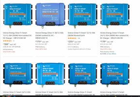
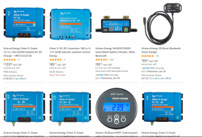
Thanks, I couldn't see that in the manual. I may spend a little more and go for the Victron Orion smart 12/12 30A, given that it has the onboard temp sensor and app. Worth an extra £50?
 
Did you want to add any solar at any point?
 
Gotcha.... in that case i would go for the Vic Orion if you have the space.

Same APP and quality kit......

If short on space. Look at the Reongy, Redarc, Ablemail, ctek units


Remember: you can parallel multiple panels to keep the VOC number low.... upto the max Amps throughput the unit can take..
Good point on multiple panels in parallel, this would have saved £ in using a combined solar/dc-dc controller. Maybe offset a little by the additional spend on another panel, fixings, brackets and cable.

I'll go for the Orion smart. I can get the 18a for £140 or the 30a for £190. I think the 18a should be fine, so hard to know before I'm using the van. Like a lot in the planning phase, making decisions for anticipated requirements is a bit if guesswork.
 
Good point on multiple panels in parallel, this would have saved £ in using a combined solar/dc-dc controller. Maybe offset a little by the additional spend on another panel, fixings, brackets and cable.

I'll go for the Orion smart. I can get the 18a for £140 or the 30a for £190. I think the 18a should be fine, so hard to know before I'm using the van. Like a lot in the planning phase, making decisions for anticipated requirements is a bit if guesswork
The leisure battery I have is this: EXV110 Enduroline Calcium Leisure Battery 12V

Would this be able to utilise a charge current of 30A anyway?
 
The leisure battery I have is this: EXV110 Enduroline Calcium Leisure Battery 12V

Would this be able to utilise a charge current of 30A anyway?
i cant find a spec sheet for that battery anywhere . . .????


(seems to be a EFB variant Silver Calcium Ca+)


so just assume its standard lead acid . . . .


which would be a charge rate of 10%-20% or ( 10A - 20A for a 100ah battery. )


That means you could run the 18A Orion . . . but you will be running it flat-out @18A charging,

that will make it run hot and start to back off the current / power.

I personally would go for the 30A version, giving you about 20A to charge the battery, plus a 10A reserve ontop to run your loads.


ultimately i would also look to upgrade that battery to a AGM at some point too. - that will give you a higher system voltage and faster recharge. also remember that SLA batteries including AGM you can only use 50% DOD of the capacity - so that 100ah battery will only give you 50ah in the real world.


and look at Lifepo4 if the budget can stretch (twice the power capacity over AGM for the same physical size)


Back
Top