Although I found I didn’t need shore power assistance to charge my LB as the solar panels kept it so full, I did put the wiring in, and included it on my schematic, and as you say it would have charged the LB directly.I was wondering about that. I'd be tempted to wire the victron directly to the LB or at least pull it out the loop to test the DC side.
You are using an out of date browser. It may not display this or other websites correctly.
You should upgrade or use an alternative browser.
You should upgrade or use an alternative browser.
dc-dc and starter battery fuse blown - advise needed
- Thread starter ArtD
- Start date
That looks like the problem to me: The Victron is supplying a voltage to the starter that is seen by the Renogy as compliant with ‘engine running’. That opens the Renogy’s gate which is a max 50A, presumably there’s sometimes enough current from the Victron to add more than another 10A to it. Fuse blows.
Maybe consider moving the Victron to the LB? The starter will be trickle-charged by the Renogy.
Maybe consider moving the Victron to the LB? The starter will be trickle-charged by the Renogy.
Last edited:
id set the Renogy dc50S to 20A and retest.
id also get a current clamp meter to you can see what current id going where.
Clamp Meters
.
id also get a current clamp meter to you can see what current id going where.
Clamp Meters
.
Let me try to go through it with clamp meter instead and set renogy to 20A although not ideal going forward but worth checking. @CJW I would rather avoid additional cabling for victron and I do not want it near driver seat (no more space there).id set the Renogy dc50S to 20A and retest.
id also get a current clamp meter to you can see what current id going where.
Clamp Meters
.
If victron max is at 30A how could it go higher by further 10A, not sure therefore what the point of max setting would be?That looks like the problem to me: The Victron is supplying a voltage to the starter that is seen by the Renogy as compliant with ‘engine running’. That opens the Renogy’s gate which is a max 50A, presumably there’s sometimes enough current from the Victron to add more than another 10A to it. Fuse blows.
Maybe consider moving the Victron to the LB? The starter will be trickle-charged by the Renogy.
The ‘malfunction’ here is that the Renogy is opening the gate when it shouldn’t. Medium term, adding the IGN cable isn’t hard - single cable, can be added without taking floors up etc if you’ve got a cable puller or something to the same effect.Let me try to go through it with clamp meter instead and set renogy to 20A although not ideal going forward but worth checking. @CJW I would rather avoid additional cabling for victron and I do not want it near driver seat (no more space there).
I’m not 100% certain, but I think when the IGN signal is pulled to earth, the Renogy will only open the gate when that signal is high.
Because amps are added. 50 max + Victron’s 30 max.If victron max is at 30A how could it go higher by further 10A, not sure therefore what the point of max setting would be?
the renogy guide calls for a 60A fuse.
and allows 50A max through unit.
so set to 20A and retest. - if its a short it will still blow.
if it holds then the DC50 is drawing 50A and melting the fuse.
another option is cheap copy fuses? that just over heat?
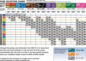
looks like you have a ANL tube fuse and not a MIDI fuse? - might be worth swapping that starter fuse for a decent MIDI one.
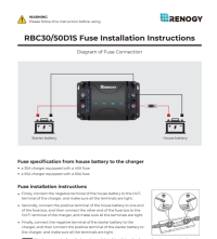
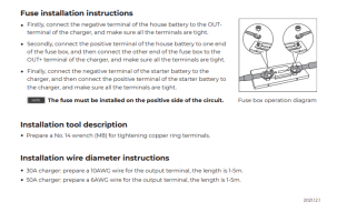


Sorry I’ve just re-read this - the 50 max referred to is what the Renogy will feed from the SB to the LB, ignoring solar.If victron max is at 30A how could it go higher by further 10A, not sure therefore what the point of max setting would be?
You’re in the right hands with @Dellmassive - I’ve suddenly gone from ‘killing time’ to ‘need to get ready to go to a wedding’. Hope you get it sorted.
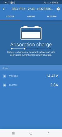
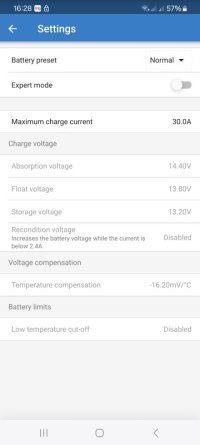
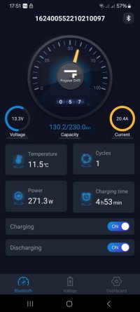
So I have run another test now setting renogy to 20A and all fine with new fuse (I had to run to halford for extra) the following shows:
1. main switch ON and victron connected (photo 1 and photo 2)
battery shows 20.4A current
renogy accordingly
2. main switch OFF and victron still connected (photo 2 and 3 and 4)
battery shows drop in current to zero within 30 seconds or so
3. however renogy after main switch is OFF and victron disconnected still shows alternator red light on - when main switch ON battery doesn't show any current on it?
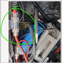
fuse picture separately also below rated 60A
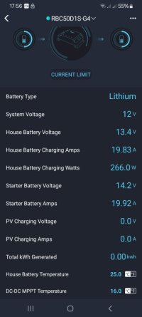
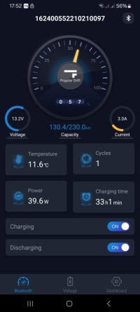
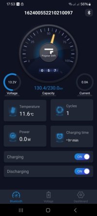
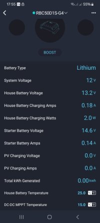
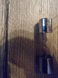


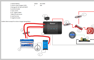
Will check tomorrow with the clamp to see how many amp run through it. although interesting knowing that reducing on renogy removed the issue.if this diagram is correct. . .
then the DC50 and Victron EHU charger wont combine..
the DC50 will pull upto 50A either from the starter battery/alternator/vic charger.
so that starter to dc50 link cable should not see more than 50A when running.
View attachment 232392
All isolator switches and battery switch should stay
on,
And shouldn't be switched when under load.
The dc50s uses algorithms to detect engine running and has hysteris to stop on/off switching too often.
You can hardly wire the iGN feed to dc50s if you wish.
Seems you're blowing a 60A fuse when pulling 50A via Renogy.... That probably down to lower voltage when the van smart alternator isn't pushing voltage, so higher current is pulled to make the same wattage.
I have checked today with the clamp meter:All isolator switches and battery switch should stay
on,
And shouldn't be switched when under load.
The dc50s uses algorithms to detect engine running and has hysteris to stop on/off switching too often.
You can hardly wire the iGN feed to dc50s if you wish.
Seems you're blowing a 60A fuse when pulling 50A via Renogy.... That probably down to lower voltage when the van smart alternator isn't pushing voltage, so higher current is pulled to make the same wattage.
when renogy set at 20A:
from victron to starter batter 23.5A-25.3A - and within that range most of the time
from battery to renogy 20.7A-21A
from renogy to LB the same
Which means it holds there is no more than set by renogy and no more than set by victron comming through. I will check with highr Amps settings
there is no issue at 30A and at 40A with renogy, but when I moved to 50A again it blown the fuse.I have checked today with the clamp meter:
when renogy set at 20A:
from victron to starter batter 23.5A-25.3A - and within that range most of the time
from battery to renogy 20.7A-21A
from renogy to LB the same
Which means it holds there is no more than set by renogy and no more than set by victron comming through. I will check with highr Amps settings
running the renogy at 50A setting is blowing the 60A fuse?
what are the voltages at the input to the Renogy at the various rates? 20,30,40A settings? - are you getting large volt drops across the link? ( post some pics or readings from the Renogy Home APP at the 4x rates)
have you swapped that starter battery fuse to a MIDI fuse yet?
.
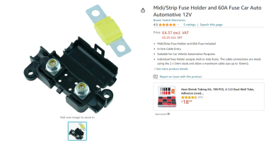
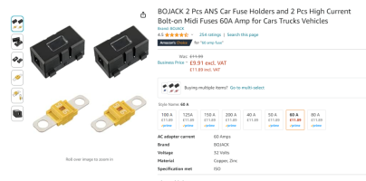
what are the voltages at the input to the Renogy at the various rates? 20,30,40A settings? - are you getting large volt drops across the link? ( post some pics or readings from the Renogy Home APP at the 4x rates)
have you swapped that starter battery fuse to a MIDI fuse yet?
.


OK tested today as follows at 20A (photo 1), 30A (photo 2), 40A (photo 3) and 50A (photo 4)
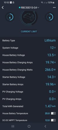
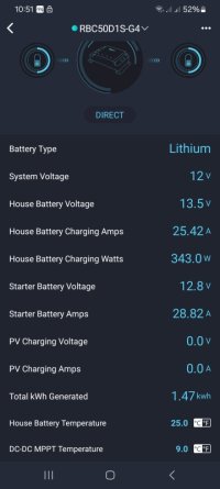
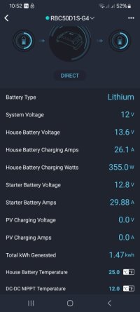
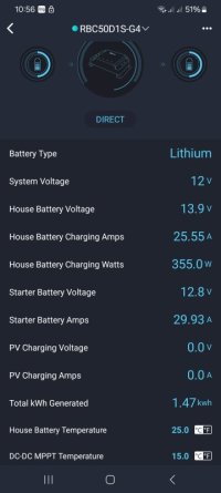
noticed today that no fuse blown when set at 50A again - but LB full too. I have also tested main switch and think whether this could be something with it i.e. last time when I switched it off and set at 50A and switched on again it blown the fuse due to surge. Could it be that there is extra amps going through somehow on top of victron charging level? Fuse at 60A still ok at the moment.
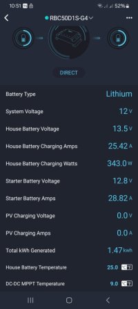
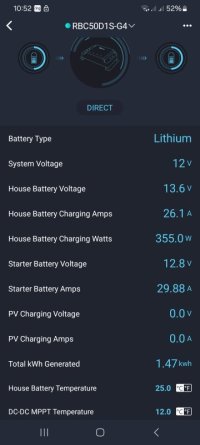


noticed today that no fuse blown when set at 50A again - but LB full too. I have also tested main switch and think whether this could be something with it i.e. last time when I switched it off and set at 50A and switched on again it blown the fuse due to surge. Could it be that there is extra amps going through somehow on top of victron charging level? Fuse at 60A still ok at the moment.


Similar threads
- Replies
- 4
- Views
- 450
- Replies
- 8
- Views
- 298
- Replies
- 5
- Views
- 618
- Replies
- 10
- Views
- 332

