[Guide] DC-DC Charger (for leisure battery) -- How I Done It --

Part-2

D+ we can run an IGN feed to this terminal

1613499427197.png

S1-S5 is the battery type setting.


1613499513859.png
.

1613499533445.png
.

1613499561966.png


cable and fuse reqs:

1613499446263.png


charge profile:
1613499596453.png

1613499606292.png
..

1613499786101.png


Now all i need to do is wait for the rian to stop so i can plug it in and start testing . . .


ill update this with results soon..

I've added the D+ wire and set the DIP switches . .


1614963461298.png

the 50A anderson connectors enable me to quickly swap out DC-DC chargers.

1614963532414.png


connected up we have a green LED and power . .

1614963574798.png

size wise in the double seat base . .

1614963615670.png
1614963636878.png
.
charging as expected . . .

1614963660517.png


ill update with some BM2 charge graphs soon . .

Edit: graphs added.

1615387361760.png1615387372340.png1615387383076.png1615387391557.png


+++

end of part2
 
Last edited:
After running through few ideas with people about wiring up a DC-DC charger i though id post it here too.

This is what i normally do for some power installs . . - Buy a Audio power Amp kit.

these kits are normally rated in Watts . . . but if you read the spec you will get an idea of what you get .

**********************

Normally you will get:

a chunky fat Red as the main feed from the starter battery to the DC-DC/Amp location.

A Fuse and fuse block to go next to the starter battery

A chunky fat black as the main ground for the DC-DC/Amp

A thinner Blue Remote/IGN feed cable that can be used as the IGN/Run feed for the DC-DC/Amp

some speaker cable - who doesn't like speaker cable.

a set of RCA audio cables, - take them indoors and use on your home stereo.

some terminals and bits and bobs to throw in the toolbox for a rainy day


**********************


so as you can see, most of the stuff you need is in the kit . . . . normally the fat red is long enough to cut down and leave some extra for the leisure battery side of the DC-DC charger.

The only extra bits of kit you may need is the second fuse for the AUX/Leisure battery . . . as maybe some crimps or lugs for the battery connections.


***********************

What size cable do i need?

Well for a DC-DC charger look at the MAX charge rate . . .say 50A For the Renogy DCS50 MPPT or Redarc BCDC1250D

then work out the distance of the cable run . . . . . say 5mtrs as an example (from starter battery to rear AUX battery location)

Example: 50A and 5mtrs/15ft cable run 4AWG or fatter 2AWG - fatter cable is better, less voltdrop and less heating when pulling current.

look at the chart and pic below, the green zone as a MIN or blue better or dark blue better still.


"The resulting figure is your system's approximate maximum current draw, whichever kind of amplifier you have. Compare this number to the numbers in the "Amperes" column in the chart below. Now figure out the cable length you'll need — that's the distance from your battery to the amplifier's mounting location. Cross-reference these two figures in the chart to determine which gauge of cable you need."

1614163998780.png

Rough Cable conversion for AWG vs mm`2

12AWG - 4.0mm`2
10AWG - 6.0mm`2
8AWG - 10mm`2
6AWG - 16mm`2
4AWG - 25mm`2
2AWG - 35mm`2
1AWG - 50mm`2
1/0AWG - 55mm`2


i always like to add a margin / headroom of 50% for peace of mind and keep the cable from heating up under load.

so as and example for a DC-DC charger, roughly double the MAX charge rate.

20A - 40A kit (Renogy)
25A - 50A kit (Renogy, CTEK)
30A - 60A Kit (Renogy, Victron Orion
40A - 80A kit (Redarc)
50A - 80-100A kit (Renogy, Redarc

***********************


Here are some example of what I've got here now :

1614163033608.png


***********

Not all Amp kits are made equal, so you need to look at the spec to see what you get,

what size cable and what size fuse.

***********


taking a look at this first one I've got : Sub-Zero Ice GL204 Wiring Kit, 2000W 2-Channel Amp Deluxe - Red: Amazon.co.uk: Car & Motorbike

Sub-Zero Ice GL204 Wiring Kit, 2000W 2-Channel Amp Deluxe - Red

  • 2000 Watt Deluxe Wiring Kit
  • For 2 Channel Amplifiers
  • 4 AWG power cable W/AGU Fuse Holder (Red 5m)
  • Ground cable - 4 AWG Black, (0.5m long)
  • RCA cable, Red/White cable with plastic plugs (5m long) Remote lead - blue (5m long), Speaker cable-blue 2.5mm cable x 2, (6m long)
  • 80A AGU Fues x2 and Holder

1614163180032.png

1614163242967.png

1614163260073.png


****************

This next one is a 1500w Branded VIBE kit (VIBE is known in the ICE and car audio market) : VIBE Audio Slick 1500 W System Car Wiring Kit: Amazon.co.uk: Electronics

you can see it comes with a better quality ANL/MIDI fuse and holder

Product Description
The Vibe Slick 1500 Watt System Wiring Kit is specifically designed to gain maximum output from high power full range systems. Combining the best full range cables from the VIBE CriticalLink TM range.

Box Contains
5m power cable. - 4awg
1m ground cable. - 4awg

5m VIBE SLICK RCA Interconnect.
5m remote turn on wire.
2 x 5m FLAT16SPK 16AWG Speaker Cable.
ANL Fuseholder.
60 amp ANL Fuse.

2 x Spade Terminals.
6 cable ties.


1614165125924.png


1614165174007.png

1614165193787.png
1614165697454.png1614165706760.png1614165720987.png1614165730343.png

********************************************


Next up is the 2000w version of the above : https://amzn.to/2NrQo45


VIBE Audio Slick 2000 W System Car Wiring Kit


Product Description
The Vibe Slick 2000 Watt System Wiring Kit is specifically designed to gain maximum output from high power full range systems. Combining the best full range cables from the VIBE CriticalLink TM range.

Box Contains
5m power cable.
1m ground cable.
5m VIBE SLICK RCA Interconnect.
5m remote turn on wire.
2 x 5m FLAT16SPK 16AWG Speaker Cable.
ANL Fuseholder.
80 amp ANL Fuse.
2 x Spade Terminals.
6 cable ties.


1614165802847.png1614165931439.png

1614166312211.png1614166322193.png

*************************

other option are premade kits like this from from Travelvolts : Wiring kit for Redarc 1240/1250, Renogy 40/50 amp,, Ablemail, Victron, Votronic. | travelvolts


1614166473914.png


or other sellers like:


1614167401858.png


*****

Resource credits:

*****
 
Ciao a tutti, installerò un riscaldatore planare e in futuro utilizzerò l'alimentazione 220v in campeggio, quale dispositivo mi consigliato? ctek d250se
caravelle t6 2018.
grazie erik
Hello everyone, I will install a planar heater and in the future I will use 220v power when camping, which device do you recommend to me? ctek d250se caravelle t6 2018. thanks erik
 
Last edited by a moderator:
DC-DC Charger (for Leisure battery) -- How I Done It --

**************************************************
Dellmassive`s -- "how I Done It" -- Thread
**************************************************
Kit List And Stuff -- How I Done It & What I Use --
**************************************************

I thought it was about time i addressed the whole DC-DC charger thing. . . .

The subject and viability is discussed at length over here > Stop/start...regen...smart Alternator... Dc-dc Charger For Leisure Battery Or Not?

View attachment 52091

Long story short the conclusion was that if you want a decent Leisure battery setup that will last a weekend, week, month etc etc ...... Then you need a DC-DC charger.

why?

Well as we found out VW went for the option of a SCR (Split Charge Relay), which worked fine for all of history before "EU6 engines with stop/start"(and EU5 T6 with stop/start as highlighted below) . . . . this new engine tech changed everything! Not only on the VW T6 but but all vehicles from all manufacturers..... Even the trusted converters got caught on the hop.

View attachment 52092

The reason for this change is "emissions standards" and MPG/fuel economy . . . the clever guys at say VW worked out that if you used the kinetic energy from deceleration/braking to "charge" the battery then you didn't need to waist precious fuel and MPG`s while driving. . . . . the net effect is that the alternator is mostly free-wheeling and only dumps power into the battery when braking.

Now this is an extremely simplified version of events .. . . in truth there is a very complex system of electronics, sensors and software controlling the whole process to ensure that we dont end up with a flat battery on Monday morning.

View attachment 52093

*****************************************************************************


What does it do?

The old "pre-EU6" system ensured a constant supply of power from the alternator when the engine was running . . . this could be seen with a multi-meter and would show a healthy 13.8v constantly that would charge the starter battery as well as any leisure battery/s that were connected to the system via the SCR. . . . This has worked great for years.

View attachment 52094

In the EU6 stop/start setup its all different, the alternator mostly free-wheels and will develop chunks of power under braking or as needed, all controlled by a computer ECU. . . . you can see this with a multi-meter, you will see 12.6v battery voltage rising to 15.2v under braking then dropping back to 12.6v when accelerating. . . . .this is no good for charging your leisure battery via a SCR.


The Ideas is the ECU will keep the starter battery at around 80% full to leave room for the REGEN braking . . .this all helps MPG and emissions. when you then connect your leisure battery and a SCR to the system you will find that your leisure battery will only ever achieve 80% SOC (state of charge) and that can fluctuate wildly (and thats assuming you are driving long enough to let the battery absorb the charge), also there is and issue of back drain . . . where by your 100% solar charged leisure battery will effectively drain its-self back down into the starter battery via the SCR once the van starts. (that has just wasted all your solar harvest)

The issue being is that in a leisure situation on a SLA (sealed lead acid) battery, you can only use the the top 50% of the battery power, its referred to a 50% DOD (depth of discharge) . . . it means on a 100Ah battery you can only use 50ah . . . beyond this the voltage drops too low to be usable and battery damage can occur... that means that if your leisure battery is only 80% charged in the first place . . . . and you can only use 50% . . . then you end up with 30% or less of your battery for your leisure applications . . . . . (this is not good and why your battery wont run your fridge and LED lights for a 3day camping trip =[ )


View attachment 52095

*****************************************************************************

A DC-DC charger will totally separate your starter battery and leisure battery systems to prevent these problems.

They work very similar to the SOLAR MPPT controllers . . . they have internal boost and buck converters that can reduce or increase the voltage/power coming from the engine bay...

Now "power is power" (that means it cant be created, but can be changed) and thats physics but what these cleaver boxes will do is take the lower voltage 80%(SOC @13.2v Float) starter battery and boost the voltage to a decent charge for your leisure setup (>100% 14.2v bst/abs/flt) . . .

They will also reduce the massive surge from the regen phase to a voltage (15.2v regen) suitable for charging.... effectively they will take the massively changing voltages a EU6 engine produces and turns it into a stable steady charging voltage to keep you leisure system at 100% charged. (>100% 14.2v bst/abs then drop to 13.2v flt as per the selected charge smart algorithm)

The great thing is these work like standard EHU battery chargers . . . they have smart 3-7 stage charging algorithms including Lithium, that will constantly monitor the SOC of your leisure setup and keep it charged to 100%. They have many built in safety features and are basically fit and forget units. . . . . Some units even have built in Solar MPPT charge controllers that offer a one-stop-shop charge solution. . . . .

Then once the battery is fully charged, the DC-DC will drop to float/maintenance mode to keep the battery at 100%.

*****************************************************************************

What happens when i turn on my Camper loads? (Inverter, Kettle, Lights, heater) -
well this is the cleaver part, most DC-DC chargers will disconnect the charging power every so often (every 100sec in the case of Redarc) to "sample" the AUX battery voltage, They use this data combined with the Current thats being drawn to determine the SOC of the battery or the Loads that are connected to the battery. . . . When you draw Loads or current from the AUX battery it will cause a slight volt drop that the DC-DC charger will detect. Using this reading plus the current drawn from the charger will make the charger move into full charge mode in an attempt to keep the battery fully charged.

The net effect is that even if your AUX battery is 100% charged @ 12.6V and the engine is running . . . . . when you switch on your loads the DC-DC charger will raise the output voltage to 14.6v or so and deliver up-to its maximum current... So effectively all your loads are being powered from the DC-DC charger and no battery power is lost (until you switch off the engine that is)

*****************************************************************************


What size DC-DC charger do i need?

This is a good question, and the answer is very similar to the "what size solar do i need?" . . . Its not just about charging your battery . . . . its also about charging you battery WHILE running your loads. So you need to account for your worst case scenario - which will be a low AUX battery while remote camping while running all your loads - at nighttime - in the rain - and its snowing etc etc ..

Joking aside i believe that the sizing of a DC-DC should account for the above, whats the point in getting in that situation, then having to switch off all your lights and fridges etc . . . just to give the battery as much charge as possible while running the engine for 20mins at nights . . . . . nope thats not right.

So take your AUX battery size say 100Ah and go with 10-20% which is a recomended charge rate for SLA/AGM etc - thats 10-20A charger .

Then measure all your loads, either with a current clamp meter, or add up all your Watts or any other way get an idea of what your worst case scenario is . . . an example may be 6amp, 10amp, 15amp, 20amp . . . whatever. Lets take 10Amp for thius example.

Add the Battery charge rate of 10-20A plus the Loads draw rate of 10A give you a figure of 20-30A.

Now you know that a 30A DC-DC is needed to fully charge your AUX battery while drawing a Load.

If you are a POWER USER like me then the sky is the limit . . . . i have 1000-1500W inverters that will draw 100A easy frona SLA/AGM battery which causes large volt SAG and depleates the battery rapidly . . . im my case i use DC-DC to offset the current draw from the battery . . . . So ill draw say 40A from the DC-DC charger, then the rest from the Aux battery. - doubling up DC-DC chargers in parrallel is also posdsible so 2x 40A DC-DC chargers will give 80A then only 20A will be drawn from the battery. (remember the cables on the system will need to handle the 80A current)

********************************************************************

What are the smart charger stages?

Adaptive three step charging, DC-DC chargers are configured for a three-step (or more) charging process: Bulk – Absorption – Float.

Bulk During this stage the controller delivers as much charge current as possible to rapidly recharge the batteries.

Absorption When the battery voltage reaches the absorption voltage setting, the controller switches to constant voltage mode. For lead acid batteries it is important that during shallow discharges the absorption time is kept short in order to prevent overcharging of the battery. After a deep discharge the absorption time is automatically increased to make sure that the battery is 3 EN NL FR DE ES SE IT completely recharged. For lithium batteries absorption time may be limited. The fixed or adaptive mode can be chosen on the battery settings (Victron unit).

Float During this stage, float voltage is applied to the battery to maintain it in a fully charged state. When the battery voltage drops substantially below this level, due to a high load for example, during at least 1 minute, a new charge cycle will be triggered.


*********************************************************************


View attachment 52096

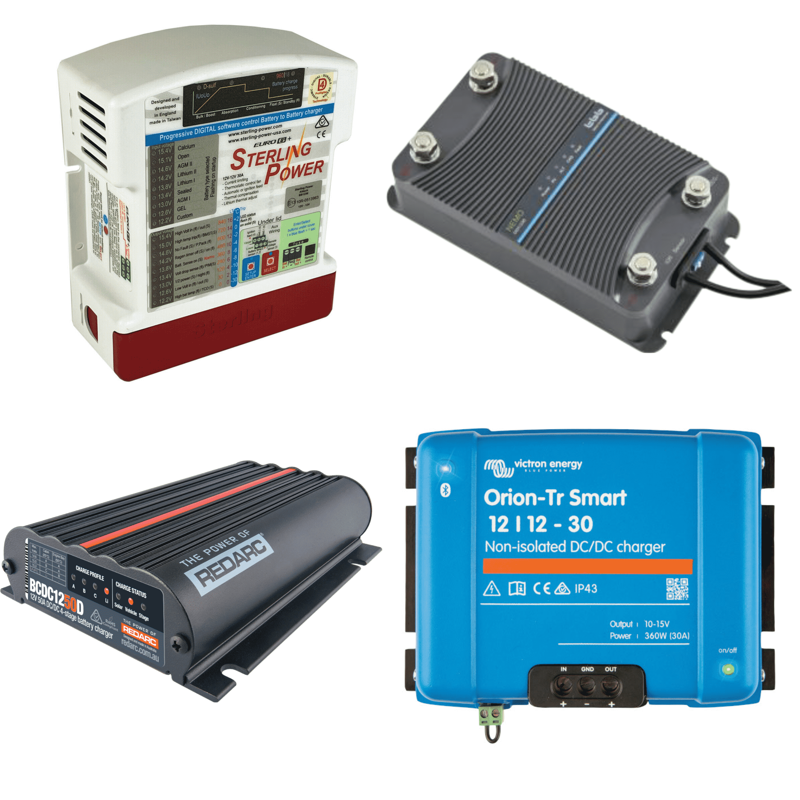
Next is to look at the available DC-DC chargers and they can/cant do:


The main contenders are below:

CTEK
REDARC
ABLEMAIL
VOTRONIC

there are other makes around.


**************************************************************


The things to look for in a DC-DC or B2b charger are:

- Max though-put or charging Amps ie 20/30/40/50/60 A.
- input voltage range ie 10-16V input for start/stop engines.
- output voltage ie - 12v as some are 24v or even 36V.
- Battery types they work with ie - AGM, SLA,LIFEPO4, Gell.
- Multi-stage smart Charging? - most are.
- Does it have a temp sensor? - some do, some dont.
- type/size of input/output terminals..
- Does it have a MPPT solar reg built in? - some do, some dont..
- can they be parralled up for power users? (some can have 4x in parrallel).

*************************************************************

The T6 "Engine Run" feed from the BCM is shown here:

View attachment 70919
T6 - Second battery wiring diagram
Second battery for transporter ( not California)
www.t6forum.com
www.t6forum.com

+12v switched on when RPM engine run is detected.

used by the OEM setup to switch a 80A relay that connects the second battery (old skool SCR)

1590166222043.png


conection : J519 BCM - T73a/3

*************************************************************

And BCM coding to activate output:

credit: @Deaky - Byte 17 Bit 4 Battery Seperating Relay active

View attachment 71162

credit: @rod_vw


View attachment 71163


**************************************************************

I personally have been running the Redarc BCDC1240LV,

and will be upgrading to the BCDC1250D shortly (added Lifepo4 battery + 50A throughput)

I will also be getting a Victron 12/12/30 to test (to see if it will work with VE-Direct)

***************************************************************


Diagrams, Schematics & Wires -- How I Done It --

***************************************************************


EDIT:


I've started a excel sheet detailing the most important details of the various DC-DC charger units as an easy to read chart.

I've attached the sheet below to download, if you have any of the missing DC-DC chargers or want to add your own . . .

download the chart edit/add in your own unit then email it back to me for uploading : dellmassive@gmail.com


******************


View attachment 69512


*****************

Hey @Dellmassive, thanks for putting this spreadsheet together, really helpful! Just wondered if you ever got round to testing whether the Redarc’s can reverse charge starter from solar?
 
Hey @Dellmassive, thanks for putting this spreadsheet together, really helpful! Just wondered if you ever got round to testing whether the Redarc’s can reverse charge starter from solar?
@bobbybasic No - the Redarc will not reverse charge the starter.

have a look over here for other options:


The AMT12-2 is a sensible off grid option.

1616319556368.png


....


or a charger on the starter for EHU option. . . . see here:


.

1616319429146.png
 
Now at this point depending on the Amp rating of your new DC-DC you may be able to just replace the relay with this mod from @travelvolts Plug and Play upgrade | travelvolts


View attachment 52401

Which make the install plug-n-play and leaves the original factory setup in place.

With a couple of remote assists from Martyn I was able to install my DTEK charger using the plug and play kit from travelvolts. Space is so tight I am not actually sure it will fit under the seat - I have tons of mysterious relays and stuff which I assume are for seat electrics and for the towbar and inverter which were fitted by the previous owner. The unit is temporarily located in front of the seat base. More on that another day.

Question: is there an alternative to the little crimps supplied in the kit which would be more secure? I don't have a tool, I simply used pliers to squish the crimps, but it took a few goes before the wires stopped tugging loose. The crimps are for the tiny little red and black wires which need to be connected due to the smart alternator, and so I would want a small, as well as secure, alternative. I've googled but quickly got lost.
Got a couple of pics?
 
those are the best crimps . . . .

maybe use the Blue, bullet or spade male/female combo so its detachable.?

the different colours is for different wire thickness,

red for thin wire,
blue for thicker,
yellow for fat,

chose the best fit terminal then crimp on.

+++

but you need the proper crimper. - https://amzn.to/3slwyWd


1618383122108.png

or just get the set:


1618383154282.png


other options are terminal strip (chock block) etc


+++


more on crimper here:


.
 
So I was able to recrimp those 2 wires successfully.

Meanwhile I haven't used the van much and the starter battery dipped below 12V so I got my mains charger out.

First of all I wanted to test the charger with the leisure battery, having just installed the Dc to DC charger. Saw some strange behaviour: the indicators on the DC to DC were switching between modes every few seconds, which was in sync with the Victron mains charger switching between Bulk and Absorption modes. This went on for a few minutes, so was not some transient thing.

In the end I disconnected my mains charger from leisure battery, and it is now charging the starter as normal, no problems.

Is the behaviour I'm seeing while mains charging the leisure battery normal? Video here.
 
@coopso

dificult to see the charger LEDS . . .

but

looks like the victron ehu charger is in RECONDITION mode?

post a screen shot from the phone app.

++

charger should be set to NORMAL AGM for starter battery.

THE CTEK will kick in when it sees the starter battery about 13.0v

we call it AUTO VSR . . . so effectively both battery's will eventually get charged.

++

you may see the charger change from ABS to BULK when the CTEK kicks in . . . thats normal as the charger is detecting the the extra draw from the ctek charging the leisure battery.
The video I posted is when the mains charger was connected directly to the leisure battery. It's in Recondition mode. The status is changing from Absorption to Bulk then back to Absorption and so on every few seconds. The lights on the CTEK are cycling between A and the battery symbol at the same time, then A only, then A and the battery symbol at the same time, and so on.
I disconnected the mains charger from the lesiure battery and moved it to under the bonnet where I connected it directly to the starter battery. It's working as normal there, so when the starter is fully charged I'll try with the leisure again - probably tomorrow.
 
So I was able to recrimp those 2 wires successfully.

Meanwhile I haven't used the van much and the starter battery dipped below 12V so I got my mains charger out.

First of all I wanted to test the charger with the leisure battery, having just installed the Dc to DC charger. Saw some strange behaviour: the indicators on the DC to DC were switching between modes every few seconds, which was in sync with the Victron mains charger switching between Bulk and Absorption modes. This went on for a few minutes, so was not some transient thing.

In the end I disconnected my mains charger from leisure battery, and it is now charging the starter as normal, no problems.

Is the behaviour I'm seeing while mains charging the leisure battery normal? Video here.
That behaviour is odd. I have the same mains charger and used to have a CTEK so have done this myself a few times. If you connected the mains charger to the Starter battery, i would expect to see what is shown in your video. The mains charger outputs (say) 14.4V (depending on which charge state it is in) which triggers the CTEK to turn on and charge the leisure battery. Depending on the state of charge, doing this can cause the voltage on the starter battery to drop so the CTEK turns off, it then charges, turns on again and eventually stays on and charges both batteries.
If you connect the mains charger to the leisure battery however, the CTEK does not reverse charge the starter battery so you should not see the CTEK turning on. Based on the CTEK behaviour, it looks as if the mains charger is connected to the starter battery in the video. I can’t see where the mains charger is connected. Are you certain it is connected to the leisure battery and/or are you sure the battery connections are the right way round on the CTEK?
If it is connected to the starter battery what you’re seeing is normal. If i ever needed to charge my leisure battery before a trip i connected my charger to the starter battery and left it for a few hours and it charged both batteries.
 
The video I posted is when the mains charger was connected directly to the leisure battery. It's in Recondition mode. The status is changing from Absorption to Bulk then back to Absorption and so on every few seconds. The lights on the CTEK are cycling between A and the battery symbol at the same time, then A only, then A and the battery symbol at the same time, and so on.
I disconnected the mains charger from the lesiure battery and moved it to under the bonnet where I connected it directly to the starter battery. It's working as normal there, so when the starter is fully charged I'll try with the leisure again - probably tomorrow.
What does the CTEK do when the mains charger is connected to the starter battery? You should be able to leave it like that and both batteries will get charged. The CTEK should show A and Battery LEDs when the mains charger is connected to the starter battery just as if it were charging with the engine running
 
What does the CTEK do when the mains charger is connected to the starter battery? You should be able to leave it like that and both batteries will get charged. The CTEK should show A and Battery LEDs when the mains charger is connected to the starter battery just as if it were charging with the engine running
Assuming the Victron history shows the most recent charge as Cycle 1, I had my mains charger (in recondition mode) connected to my starter battery for 6 hours 10 yesterday. The CTEK didn't come alive at all as far as I could see. I checked a few times including when I eventually switched the charger off. I have it connected now (normal model) and the CTEK is still in current saving mode (power LED flashing).
Screenshot_20210418-164122.jpg
 
CTEK is connected as follows: brown cable from CTEK negative to leisure negative; black sheathed cable from CTEK OUT (goes to the travelvolts relay plug kit); red cable from CTEK A (goes to the travelvolts relay plug kit). The small wires from CTEK are connected as follows: black/red to black (goes to the travelvolts relay plug kit) and red to red (goes to the travelvolts relay plug kit) (my factory leisure is an AGM type battery).
 
Just tried connecting the mains charger to the leisure battery, and the CTEK is no longer acting strangely. Both the A and the battery logo LEDs are solid, which if I'm right means both the starter and the leisure battery are charging. Happy days! The only thing I have changed is I noticed the battery monitor I have for the starter wasn't reachable, so I disconnected the black wire from the earthing bolt - which it was sharing with the mains charger - and connected it to a different earth. Maybe this was the problem...?
 
Just tried connecting the mains charger to the leisure battery, and the CTEK is no longer acting strangely. Both the A and the battery logo LEDs are solid, which if I'm right means both the starter and the leisure battery are charging. Happy days! The only thing I have changed is I noticed the battery monitor I have for the starter wasn't reachable, so I disconnected the black wire from the earthing bolt - which it was sharing with the mains charger - and connected it to a different earth. Maybe this was the problem...?
It sounds to me like your starter and leisure batteries are connected the wrong way round. I’m not familiar with the kit you’re using from Travelvolts so I’d suggest a simple test to confirm which is connected to which point on your CTEK. Either trace the wires all the way through or disconnect your leisure battery by removing the earth. Then test for 12V at the two points on the CTEK where the batteries connect to see which one you have removed.

When A and battery LEDs are both lit it means leisure is being charged from starter. That should not happen if you connect a mains charger to leisure. But it will if you connect to starter. This is partly what makes me think they may be connected the wrong way round
Thanks for replying.
"disconnect your leisure battery by removing the earth" - you mean remove the clamp from the negative terminal of the leisure battery?
"Then test for 12V at the two points on the CTEK where the batteries connect" - I do have a multimeter but no idea how to use it!
 
Back
Top