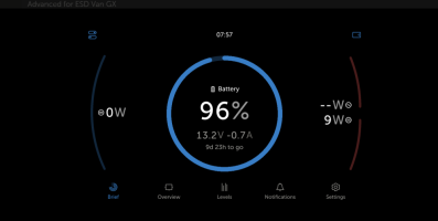
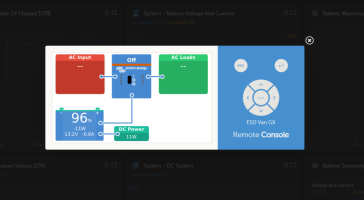
[Guide] Renogy IP67 50A DC-DC Charger + MPPT (for leisure battery) -- How We Done It --

Dellmassive

T32 204 DSG LWB SLN PV MY18 & T30 SWB KMB MY67
VCDS User
Moderator
VIP Member
T6 Master
[Guide] Renogy IP67 50A DC-DC Charger + MPPT (for leisure battery) -- How We Done It --

..

with thanks to a Forum Member for buying this for himself, but sending it to me first to test it out.

we have the new

..
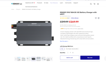
RENOGY IP67 50A DC-DC Battery Charger with MPPT​


1707482104254.png

RENOGY 12V/24V IP67 50A DC-DC Battery Charger with MPPT

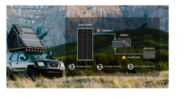
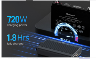
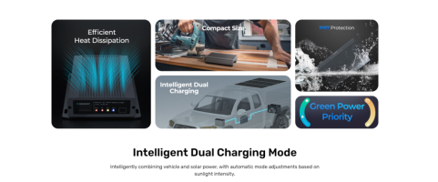
Introducing the RENOGY IP67 50A DC-DC Dual Input Battery Charger with MPPT, a slim, waterproof dual charging solution perfect for confined spaces. Equipped with intelligent boost and buck logic, it seamlessly accommodates 12V/24V-12V/24V voltage systems, elevating DIY possibilities to the uttermost. Renogy's exclusive intelligent charging logic prioritizes solar energy, efficiently charging your house battery while easing the load on generators. This innovative product combines vehicle and solar power, automatically adjusting modes based on sunlight intensity. Maximizing energy utilization, it boasts a robust 50A current and an impressive 720W output power. Renogy IP67 Dual Input Battery Charger seamlessly switches to solar charging in ample sunlight and smoothly transitions to generator charging during low light, ensuring uninterrupted device power. Embrace an eco-conscious charging experience without compromising efficiency or space, redefining sustainable energy utilization.


-A dual charging solution with 12V/24V boost and buck logic.
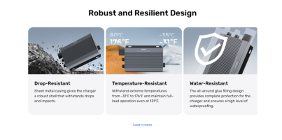
-Compact & lightweight with IP67 waterproof rating.
-Auto-switching charging mode while prioritizing green power.
-CE, FCC, RoHS certified with comprehensive test reports.
-Bluetooth Energy Monitoring with wired CAN communication.


++++++++++

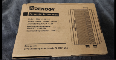
SPECIFICATION
System Voltage: 12V/24V - 12V/24V

Solar Input Voltage: 50 VDC

Output Voltage: 9-16 VDC

Alternator Input: 13.5-16 VDC

Maximum Output Current Rating: 50A

Output Power: 720W

Battery Types: AGM/SLD , GEL ,FLD ,LI,USER

Input Fuse Rating: 75A-100A

Output Fuse Rating: 75A-100A

Charging Efficiency: 0.94

Temperature Compensation: -3mV / ℃ / 2V (Non-Lithium);0mV / ℃ / 2V; no compensation (Lithium)

Idle Power Consumption: <100mA

GENERAL DATA
Terminal Range: 8AWG-4AWG

Communication Protocol: Modbus ; RV-C

Operating Temperature Range: '-31℉ to 176℉/-35℃ to 80℃

Storage Temperature Range: -40℉ to 176℉/-40℃ to 80℃

Humidity: 0%-95%, No Condensation

Maximum Operating Altitude: 3500m

Enclosure Rating: IP67

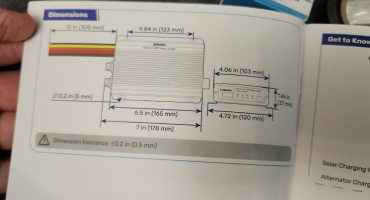
Dimensions: 7.01 x 4.78 x 1.47 in/178.2 x 121.5 x 37.5mm

Weight: 4.10 lb / 1.86 kg

Certification: CE;RoHS;FCC Part 15 class B

++++++++++
1707482150127.png1707482159769.png1707482183531.png1707482173335.png


+++


+++


.
 
lets see what we get. . .


1707482359956.png


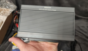
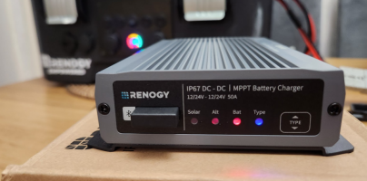
size wise its nice and small. . . and feels very durable with its all metal construction . . .


1707482422106.png
1707482373512.png


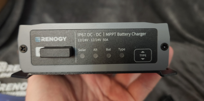
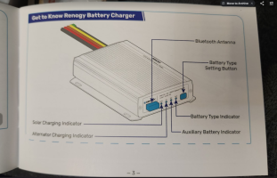
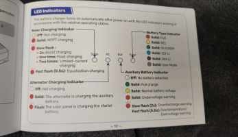
on the fron there is a mode button and 4x status LEDS, - the little sticky out bit is a plastic window in the metal case for the BT,

yes this unit has built in BT + APP support.


1707482514933.png

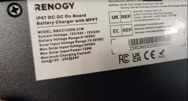
spec wise we have:

9v-16v Smart ALT input,

15-50v Solar PV input,


1707482542761.png
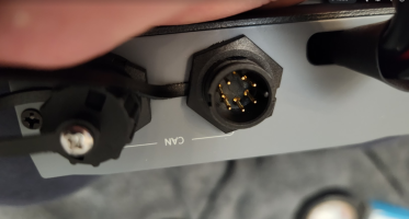
round the back we have this twin CAN Bus plugs - for connecting up to other CAN enabled Renogy Kit,

plus the IP67 loom, that has about 30cm of cable.

1707482733031.png
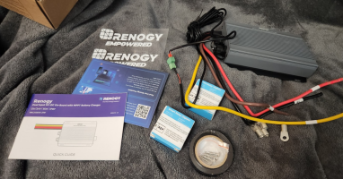
in the pack you get:

crimp terminals for a MIDI fuse holder,
role of leccy tape,
mounting screws,
a temp sensor,
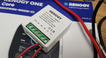
Two ZIGBEE wifi switches


1707482844643.png

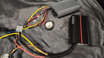
cable wise. . . we see something new here.

no remote voltage sampling,

and no IGN switch input.

this charger uses voltage detection to switch on (trigger point is adjustable to suit your install)


1707482951842.png

.

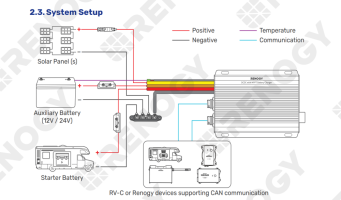
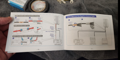
the install guide shows some nice details for fitting.

but not so sure about the twisty tape-y bit.. . .

1707482991307.png1707483002053.png1707483020502.png1707483064951.png1707483011896.png
+++++++
see the install guide here:


++++++++

.
 
  • Like
Reactions: CAB
Hmmm - see this before?

well that what i thought. . .
have a look at this,


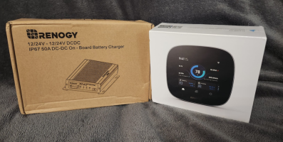
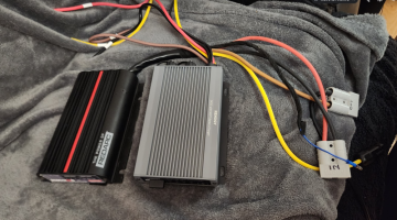
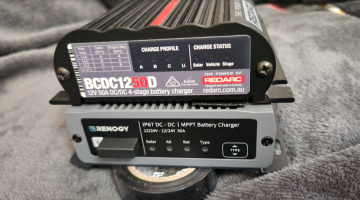
here is a REDARC BCDC1250D and the Renogy IP67 next to each other.


1707483141666.png1707483170749.png1707483160159.png1707483150196.png


...


1707483358382.png


have Renogy white boxed a Redarc?

have they copied it?

are they working together?

is this the Redarc we always wanted - with BT & APP?


even the cable colours / style etc etc - all the same.

..
 
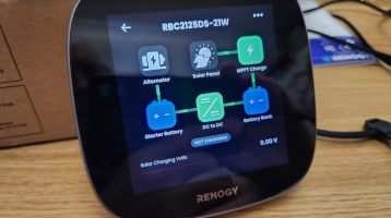
RENOGY Core 1 . . . .

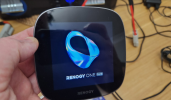
the next box is the core ONE,

its a BT/CAN box that has WIFI,

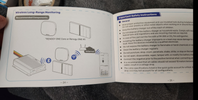
the idea is that its fitted in the van and conects to your Renogy kit, (battery, dc-dc,mppt, shunt etc etc ) via BT or cable.

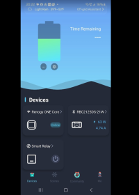
then - when the unit is connect to 2.4G WIFI and logged into your DC Home Renogy APP account,

you can monitor the van remotely for anywhere with internet access. ( a bit like Victron VRM?)

The DC-Home APP is free,

but the PC monitoring portal is a paid option.

in the box:

bracket,
screws
12v power lead,


1707483643574.png

size wise its bigger than the web pics show. . .


1707483692493.png

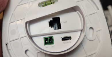
round the back you can use USB-C to power it up.

1707483717749.png

1707483731719.png

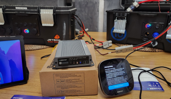
here you can see a rough size comparision. . .

1707483755501.png

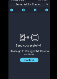
once conected to your 2.4G wifi (not 5G !)

it asks for FW updates etc. . .


1707483806402.png


.


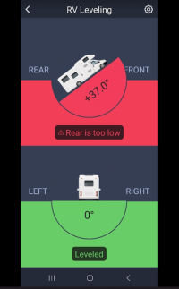
there is a nice leveing page that can be used for your Van.

1707483863019.png


once connected to your phone APP, you can add devices. . .

it found the DC-DC charger easy and added it..


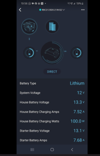
1707483944953.png


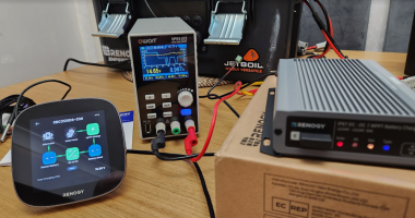
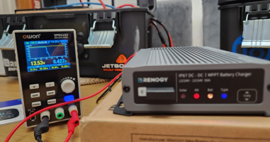
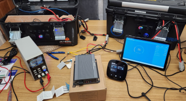
connecting up a PSU on the Solar side, the charger kicks into life. . .


1707483987611.png


+++++

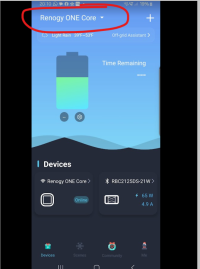
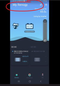
one thing to note is that when you have ONE,

the DC Home APP has two modes . . .

internet based ONE Core mode like this. . .

1707484104287.png


and local BT mode, like this.

1707484134655.png


but it looks like the DC-DC charger can only be connect to one device, either the ONE or your phone,


so to get the DC-DC to conect localy to the Phone APP via BT, . . . we had to turn off the ONE.


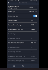
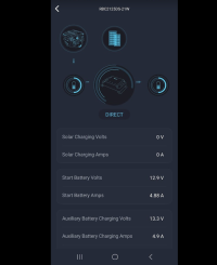
then we could get to the settings page of the DC-DC charger - that wasn't available from the ONE side of things.


1707484256808.png


...


in the setting i was able to tweek the default Lifepo4 settings and current limit the unit from 50A to 10A for testing.


+++


one of the main differences is now NO IGN feed.


the unit is auto matic. . .


and there is a setting in the same menu to set the trigger point . .


it was set to 13.8v, so i tweeked it to 13.5v to test.

sure enough as soon as the voltage was above that point the unit come to life,

indicating ALT charge.

1707484514663.png

1707484474079.png1707484491612.png


ill get the unit plugged into the van for some higher current testing and Temp readings.


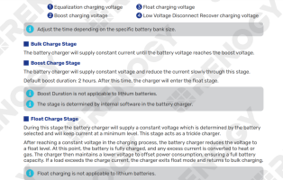
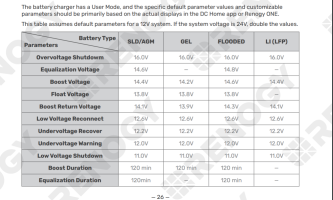
Charge profiles:


6.4.Activate Lithium BatteriesThe battery charger can activate connected lithium batteries. Lithium batteries may enter sleep modewhen the in-built protection is triggered. In such case, the battery charger provides a small current toreactivate the sleeping lithium battery. The lithium battery can be charged normally after successfulactivation.By default, the lithium activation function is enabled in the battery charger. You can disable it inthe DC Home app.


█ Operation ConditionSet the battery type of the battery charger to LI or USER. For details, see “6.1. Set a Battery Type”.█ Operation Logicz For 12V Lithium BatteryIf the battery voltage drops below 9V, the battery charger automatically activates the activationfunction (on the premise that the activation function is enabled in the DC Home app) and continuesto charge the battery using constant voltage until the battery voltage reaches 14.4V.


1707484683483.png


8.2.Charging LogicThe battery charger allows you to charge the auxiliary battery with a starter battery connected to analternator, with solar panels connected directly to the battery charger, or with both solar panel andstarter battery. The charging logic depends on the connection method.The battery charger employs the “Solar Power Green Priority” logic for charging. The battery chargerdetermines the charging source by assessing the adequacy of solar power using the following formula.Solar-generated Power = LowSolar Current Shuntdown x Output Voltage of the Battery ChargerYou need to customize the “LowSolar Current Shuntdown” through the DC Home app.Please refer to the actual displays in the DC Home app for the default value and setting range ofLowSolar Current Shuntdown.The maximum charging power from the battery charger is not affected by the system voltage andremains at 720W.█ When Solar-Generated Power is AdequateThe battery charger charges the auxiliary battery using solar power only when the solar-generatedpower is adequate. For details, see the table below:Working Conditions Stop ConditionsSolar input voltage > 15VAfter a delay of 10 seconds, the battery chargerwill exclusively utilize the current provided by thesolar panel for charging.Solar input voltage < 15VThe battery charger stops exclusively using thesolar panel for charging.█ When Solar-Generated Power is Slightly InadequateThe battery charger adopts both solar power and the starter battery to charge the auxiliary batterywhen the solar-generated power is slightly inadequate.Starter BatteryNominal Voltage Working Conditions Stop Conditions12VSolar input voltage < 15VandStarter battery voltage > 13.2VSolar input voltage > 15VorStarter battery voltage < 12.7V24VSolar input voltage < 15VandStarter battery voltage > 26.4VSolar input voltage > 15VorStarter battery voltage < 25.4VThe parameters in the above table are default values, and you can customize them throughthe DC Home app. Please refer to the actual displays in the DC Home app for the specificcustomization range.Please consult the vehicle manufacturer before modifying the voltage values for the workingand stop conditions of the starter battery. Failure to do so may result in the starter battery beingdepleted due to excessive discharge.— 34 —█ When Solar-Generated Power is Severely InadequateWhen solar power is severely inadequate, the battery charger charges the auxiliary battery by utilizingonly the starter battery.Starter BatteryNominal Voltage Working Conditions Stop Conditions12VSolar output current <LowSolar Current ShuntdownandStarter battery voltage > 13.2VAfter 15 seconds, the battery chargerwill utilize the current provided by thestarter battery for charging.Solar output current >LowSolar Current ShuntdownorStarter battery voltage < 12.7V24VSolar output current <LowSolar Current ShuntdownandStarter battery voltage > 26.4VAfter 15 seconds, the battery chargerwill utilize the current provided by thestarter battery for charging.Solar output current >LowSolar Current ShuntdownorStarter battery voltage < 25.4VThe parameters “LowSolar Current Shutdown” and “Starter Battery Voltage” in the above tableare default values, and you can customize them through the DC Home app. Please refer to theactual displays in the DC Home app for the specific customization range.Please consult the vehicle manufacturer before modifying the voltage values for the workingand stop conditions of the starter battery. Failure to do so may result in the starter battery beingdepleted due to excessive discharge.█ Trickle Charging Starter BatteryOnce the auxiliary battery is fully charged, the battery charger will utilize the solar panel to provide atrickle charge to the starter battery.Starter BatteryNominal Voltage Working Conditions Stop ConditionsMaximum ChargingVoltage for theStarter Battery12Vz Auxiliary batteryfully chargedz 6V < StarterBattery Voltage <13.2VThe solar panel continuouslycharges the starter battery for 1minute, followed by a 30-secondpause. During this time, the voltageof the starter battery is monitored.If the starter battery voltage isgreater than 13.2V, charging will bestopped. Otherwise, the chargingcycle will continue.13.8V24Vz Auxiliary batteryfully chargedz 12V < StarterBattery Voltage <26.4VThe solar panel continuouslycharges the starter battery for 1minute, followed by a 30-secondpause. During this time, the voltageof the starter battery is monitored.If the starter battery voltage isgreater than 26.4V, charging will bestopped. Otherwise, the chargingcycle will continue.27.6V
 
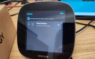
ZIGBEE . . . . ( wifi smart switch in the van )

we had two Zigbee wifif switches in the box,


1707484608677.png


powering up the Zigbee with a 12v supply,

the unit is visable to the core ONE,


and super easy to add,

once added you can see and use them in the HOME app or via the ONE screen.


1707484966537.png


licking the APP or ONE screen will toggle the Zigbee on/off.

there is also a button on the unit that does the same.

1707485001488.png


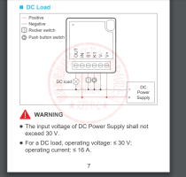
you can wire a switch to S1 or K1 to toggle on/off as well.


1707485057213.png


you can then wire up the switch 12v output to run your kit.

12vdc up to 15A

ie lights or whatever.


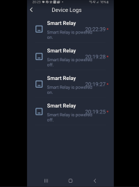
there are logs and scenes that you can set cause=effect routines.


1707485189045.png

a great little addition. . .


1707485210216.png


'''


///
 
Last edited:
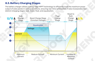
Charging stages:


1707484806670.png1707484825500.png


....


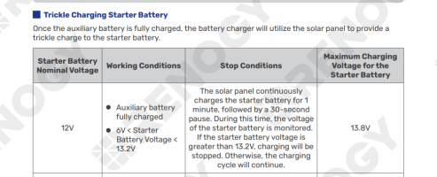
Trickle Charging Starter Battery

Once the auxiliary battery is fully charged, the battery charger will utilize the solar panel to provide atrickle charge to the starter battery.Starter BatteryNominal Voltage Working Conditions Stop ConditionsMaximum ChargingVoltage for theStarter Battery12Vz Auxiliary batteryfully chargedz 6V < StarterBattery Voltage <13.2VThe solar panel continuouslycharges the starter battery for 1minute, followed by a 30-secondpause. During this time, the voltageof the starter battery is monitored.If the starter battery voltage isgreater than 13.2V, charging will bestopped. Otherwise, the chargingcycle will continue.13.8V


.

1707484863047.png
 
  • Like
Reactions: CAB
Watching your testing with interest @Dellmassive - if this doesn't have the 25a DC-DC limitation when solar is running of the DCC50S then it could be a really good alternative to a Victron DC-DC, MPPT and BMV...

Looking at the charging logic section it seems they've fixed this as it allows charging either from only SB, or only PV, or both PV and SB if solar power is low. No mention of any limitations so I'm hoping it will use the solar and then 'fill in' using SB power up to 50a (when required).

I look forward to your results!
 
Last edited:
Watching your testing with interest @Dellmassive - if this doesn't have the 25a DC-DC limitation when solar is running of the DCC50S then it could be a really good alternative to a Victron DC-DC, MPPT and BMV...

Looking at the charging logic section it seems they've fixed this as it allows charging either from only SB, or only PV, or both PV and SB if solar power is low. No mention of any limitations so I'm hoping it will use the solar and then 'fill in' using SB power up to 50a (when required).

I look forward to your results!
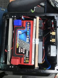
I fitted one of these units last week, the blurb states that it prioritises PV when both PV and the alternator are running. I've attached a picture of my install for size

IMG_2509.jpg
 
I fitted one of these units last week, the blurb states that it prioritises PV when both PV and the alternator are running. I've attached a picture of my install for size

View attachment 229274
Yeah, so the issue with the DCC50S was that the alternator charging was limited to 25a if the charger saw any solar input, so on a dull day, driving somewhere with low solar input (say a few amps) you'd only get maximum 25a from the alternator. You'd only get the full 50a if you had no solar, or if you turned off the solar input, or if solar was also putting in 25a.

So realistically on a dull day you'd be limited to 30a or so when driving.

Which, when compared to using a separate DC-DC and MPPT where you could easily get 30a or 50a, or more from the DC-DC and another 15a or 30a from solar was a bit lacklustre, especially if you had a big 230ah LiFePO4 battery.

I'm hoping this one fixes that 'feature' and you can get the full 50a regardless of much or how little the PV is putting in. So if the PV is putting in 5a (as per the above example), instead of the SB only adding 25a, it can add 45a. Seems like it's more flexible with the settings too, you can set when the PV to SB switchover is, which is also good.
 
Hi, i have a very short question about Renogy 50A DC-DC charger with MPPT, hope it is a right place to ask it.
We are choosing a solar panel and we are currently looking at two 200W models. The first panel's Vmp is 18,7 and Voc is 22,45 and the second ones Vmp is 20,7 and Voc is 24,84. Is that correct that we can't use the second one as it can produce more than 25V in cold weather? And what about the first one? Is 22,45V safe to use with Renogy device?
Would appreciate your help!
 
The new IP67 Renogy has a 50v VOC.


And the new version of the dc50s also has 50v VOC.


VOC is the max voltage you will see, off load in the cold.


Vmp is the voltage you see when running at max power and generating current.


VOC is the voltage that is important.


Older Renogy have a VOC max of 25v


Newer units have 50v VOC max.
 
The charging limit of the old DCC50S current wise isn't an issue when driving around as you just isolate the solar input and get your potential 50A from the starter battery.
The higher solar input voltage of this and the later DCC50S is a plus as it allows more options with solar panel choice and series or parallel connection.
I'll be honest as an old duffer I find all the Bluetooth/WiFi stuff daunting and slightly off putting and prefer KISS options.:sick:
 
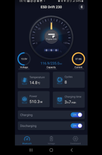
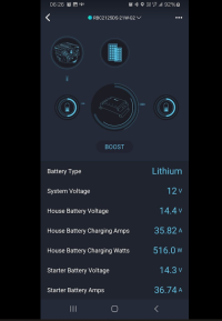
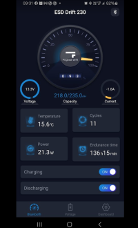
HEAT.


has this running 20-30A with no heat issues. . .

but changing the setting to 40A charge rate and things start to warm up. . .


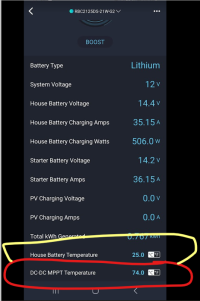
this is 40A setting, after about an hours driving BULK charging the 230ah Fogstart battery.

yep 75degC - and the whole case was very hot, ( in RED)

the 25c in yellow is the default temp with no temp probe connected - the install guide says leave the temp sensor disconnected for Lifepo4 battery's.


1708251998152.png

basically running 37.8A into the battery for an hour solid before the drive cycle was over. . .


1708252123276.png1708252139296.png


so be mindful and let the unit have fresh air to breath.
 
Maybe a stupid question but can the negative bus bar (solar and leisure battery) just be connected to a common ground and then only a positive cable ran from the starter battery? As the starter battery will be grounded anyway?
 
Maybe a stupid question but can the negative bus bar (solar and leisure battery) just be connected to a common ground and then only a positive cable ran from the starter battery? As the starter battery will be grounded anyway?
Yes
 
Have you done any more testing on this @Dellmassive or has it gone back to it's original owner?
its being returned to the owner. . . what would you like to know?

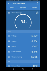
I've put the Victron Orion XS back in.

+ Fogstar Drift 230
+ Vic` BMV712
+ Vic` Cerbo
+ Renogy 1000w Inverter

..
1710316492908.png1710316502890.png


+++

1710316591057.png1710316617818.png1710316645165.png1710316653436.png1710316637080.png1710316676904.png
 
Ah no worries, I was just interested really in how it handles PV and SB charging at the same time - we know it prioritises PV but I wondered if it was getting 5 or 10a from PV would it then use DC-DC for the remainder up to 50a. Ie is it better than the DCC50S which we know can only do 25a from the SB is there's any PV coming in.

The user manual talks about some clever charging logic but doesn't really go into the numbers (aside from the PV cut off).
 
Gotcha,

i did think about that myself, but had already swapped it out.

I've asked Renogy - lets see what they come back with
 
@Dellmassive thanks for that, hopefully Renogy come back with good news!

Another thing - I can't see any mention of a low temperature cut off on this unit, only that the temp sensor is used for charging compensation. Did you see any option for low temperature charge blocking in your tests? @jimc91 might be able too answer too

I'm quite tempted by the eco-worthy 100ah battery but it has no low temperature protection so if the Renogy doesn't have it either, that's a no go. Ta! :thumbsup:
 
Back
Top