You are using an out of date browser. It may not display this or other websites correctly.
You should upgrade or use an alternative browser.
You should upgrade or use an alternative browser.
[Guide] DC-DC Charger (for leisure battery) -- How I Done It --
- Thread starter Dellmassive
- Start date
There are of course many different options as you know . . . and Threads to cover all that.Thanks Lee. Or should I say Mr. Renogy! Been looking at your threads so will work out how to do it all now.
Thanks bud.
I've just started adding the "Short Cut" option for people that say "Just tell me what i need Dell"
Once you choose your kit, look for a local. . . . .
Car audio installers,
Van converters,
Auto electrician,
Caravan workshop,
Etc,etc.
Car audio installers are the best choice, as they are used to installing high powered amplifiers etc.... So used to big power.
Car audio installers,
Van converters,
Auto electrician,
Caravan workshop,
Etc,etc.
Car audio installers are the best choice, as they are used to installing high powered amplifiers etc.... So used to big power.
- NEW Test -
- CTEK D250SE -
i finally got around to getting a CTEK D250SE from a forum member for some testing. - https://amzn.to/3jbFJqP

what the spec says.
Dual input 20A charger with selectable charge voltages
The D250SE is a fully automatic, 5 step charger that supplies up to 20A of power to any 12V lead-acid or lithium* service battery from 40–300Ah. It has selectable charge algorithms for AGM and lithium* batteries and can use power through its dual input from alternator and solar panel. When the service battery is fully charged, the D250SE will automatically redirect maintenance charge power to the starter battery. The D250SE can maintain a stable output up to 20A to vehicles fitted with smart ECU controlled alternators and also has a temperature sensor for optimised charging, regardless of weather conditions. *) 12V lithium batteries (LiFePO4, Li-Fe, Li-iron, LFP)
Features
Battery capacity40–300 AhCharging categoryDC chargingBack current drain*Corresponding to less than 1 Ah/monthBattery voltage12 VBattery chemistryLead acid; Lithium-ionAmbient operating temperature-20 ˚C to +50 ˚C (- 4 °F to +122 °F)Input11.5–23 V, 25 AOutput14.4/14.7 V, 20 A, lead-acid battery types. 14.2 V, 20 A, LiFePO₄.Ripple**Less than 4 %Battery types12 V:; WET; MF; Ca/Ca; AGM; EFB; GEL; LiFePO₄Degree of protectionIP65Gross weight (unit in box)0.9 kgDimensions (L x W x H)192 x 110 x 65 mmNet weight (unit with cables)0.7 kgMPPTYesWarranty2 yearsWarranty, infoLimited Warranty
The older version is the D250SA
the newer version is the D250SE - (this one has a lithium profile)
This is our one..


..
install wise its failrly simple.
POS from starter - (Fused appropriately for the gauge and cable run)
POS from Leisure battery (LB) - (Fused appropriately for the gauge and cable run)
NEG to GND/Chassis
SOLAR PV POS (SOLAR PV NEG to chassis)
Battery select black wire - (+12v for Lithium)
EU6 select red wire - (+12v for stop/start EU6)
following the guide:


++++++++++++
we will be wiring it up with the standard 50A Anderson connectors so we can swap units in/out easily.
starting with a few connectors and heat shrink plus crimps.

we make us a few link cables . . . using 8AWG Silicone cable.


we end up with this . . .

Battery select black wire - (+12v for Lithium)
EU6 select red wire - (+12v for stop/start EU6)
dropping it into the van seat bench base with HD Velcro. . . .

..
we can start testing.
The Auto VSR feature kicks in around 13.1V. (with no IGN feed connected)
with the IGN feed the charger will start/stop following the Engine BCM run signal.

we can see a solid 20A from the charger,
18.85A logged going into the Poweroad 100Ah Lifpo4 battery.

it looks a bit messy . . . but its all functional and safe.

..
you can see the charger reacting the van engine on/off/on . . .

and the BM2 showing the battery charging as the voltage starts to increase. . . . . . .

Temp wise the Lithium battery will pull MAX current from the charger . . . . so 20A from this unit.
after about 30mins the front of the charger was very warm to the touch, but not too hot.
the rear of the unit seemed to stay cool.
++++++++++++++
with a 100ah or above Lithium a 20A charger may not be the best or fastest way to charge it . . .
but the lower 20A current means you can use smaller gauge cables and keep any excessive heat under control
ill run the charger for a month and see how it performs.
solar is a bit weak atm, but it will charge upto 20A from PV (you must keep under the 23v VOC max)
and once the LB is charged it will "reverse charge" trickle charge the starter ar 1A max. (not great, but better than nothing i suppose)
++++++++++++++
related pics of testing . . . .


....
+++++++++++++
Parts list:
anderson connector - https://amzn.to/3DUdTHA
heat shrink kit - https://amzn.to/3lR4biY
8awg silicone wire - https://amzn.to/3aPpDhL
hs-16 crimpers - https://amzn.to/3FWolA8
10-8 terminals - https://amzn.to/3lQEpLH
crimp terminals - https://amzn.to/3aPBs7U
14awg wire - https://amzn.to/3AUh6ot
hd velcro - https://amzn.to/3prZ5fl
ANL/MIDI fuse box - https://amzn.to/3vp2ZWV
+++++++++++++
- CTEK D250SE -
i finally got around to getting a CTEK D250SE from a forum member for some testing. - https://amzn.to/3jbFJqP
what the spec says.
Description
Dual input 20A charger with selectable charge voltages
The D250SE is a fully automatic, 5 step charger that supplies up to 20A of power to any 12V lead-acid or lithium* service battery from 40–300Ah. It has selectable charge algorithms for AGM and lithium* batteries and can use power through its dual input from alternator and solar panel. When the service battery is fully charged, the D250SE will automatically redirect maintenance charge power to the starter battery. The D250SE can maintain a stable output up to 20A to vehicles fitted with smart ECU controlled alternators and also has a temperature sensor for optimised charging, regardless of weather conditions. *) 12V lithium batteries (LiFePO4, Li-Fe, Li-iron, LFP)
Features
- Battery separation replacing diodes and VSR relays
- Selectable AGM option – 14.4V or 14.7V
- Maximised charging for better battery life and performance
- Temperature sensor to compensate for hot or cold conditions
- Splash and dust proof (IP65)
- Compatible with SMARTPASS 120, SMARTPASS 120S for the ultimate 140A power management solution
- 2-year warranty
Technical data
Battery capacity40–300 AhCharging categoryDC chargingBack current drain*Corresponding to less than 1 Ah/monthBattery voltage12 VBattery chemistryLead acid; Lithium-ionAmbient operating temperature-20 ˚C to +50 ˚C (- 4 °F to +122 °F)Input11.5–23 V, 25 AOutput14.4/14.7 V, 20 A, lead-acid battery types. 14.2 V, 20 A, LiFePO₄.Ripple**Less than 4 %Battery types12 V:; WET; MF; Ca/Ca; AGM; EFB; GEL; LiFePO₄Degree of protectionIP65Gross weight (unit in box)0.9 kgDimensions (L x W x H)192 x 110 x 65 mmNet weight (unit with cables)0.7 kgMPPTYesWarranty2 yearsWarranty, infoLimited Warranty
The older version is the D250SA
the newer version is the D250SE - (this one has a lithium profile)
This is our one..
..
install wise its failrly simple.
POS from starter - (Fused appropriately for the gauge and cable run)
POS from Leisure battery (LB) - (Fused appropriately for the gauge and cable run)
NEG to GND/Chassis
SOLAR PV POS (SOLAR PV NEG to chassis)
Battery select black wire - (+12v for Lithium)
EU6 select red wire - (+12v for stop/start EU6)
following the guide:
++++++++++++
we will be wiring it up with the standard 50A Anderson connectors so we can swap units in/out easily.
starting with a few connectors and heat shrink plus crimps.
we make us a few link cables . . . using 8AWG Silicone cable.
we end up with this . . .
Battery select black wire - (+12v for Lithium)
EU6 select red wire - (+12v for stop/start EU6)
dropping it into the van seat bench base with HD Velcro. . . .
..
we can start testing.
The Auto VSR feature kicks in around 13.1V. (with no IGN feed connected)
with the IGN feed the charger will start/stop following the Engine BCM run signal.
we can see a solid 20A from the charger,
18.85A logged going into the Poweroad 100Ah Lifpo4 battery.
it looks a bit messy . . . but its all functional and safe.
..
you can see the charger reacting the van engine on/off/on . . .
and the BM2 showing the battery charging as the voltage starts to increase. . . . . . .
Temp wise the Lithium battery will pull MAX current from the charger . . . . so 20A from this unit.
after about 30mins the front of the charger was very warm to the touch, but not too hot.
the rear of the unit seemed to stay cool.
++++++++++++++
with a 100ah or above Lithium a 20A charger may not be the best or fastest way to charge it . . .
but the lower 20A current means you can use smaller gauge cables and keep any excessive heat under control
ill run the charger for a month and see how it performs.
solar is a bit weak atm, but it will charge upto 20A from PV (you must keep under the 23v VOC max)
and once the LB is charged it will "reverse charge" trickle charge the starter ar 1A max. (not great, but better than nothing i suppose)
++++++++++++++
related pics of testing . . . .
....
+++++++++++++
Parts list:
anderson connector - https://amzn.to/3DUdTHA
heat shrink kit - https://amzn.to/3lR4biY
8awg silicone wire - https://amzn.to/3aPpDhL
hs-16 crimpers - https://amzn.to/3FWolA8
10-8 terminals - https://amzn.to/3lQEpLH
crimp terminals - https://amzn.to/3aPBs7U
14awg wire - https://amzn.to/3AUh6ot
hd velcro - https://amzn.to/3prZ5fl
ANL/MIDI fuse box - https://amzn.to/3vp2ZWV
+++++++++++++
Last edited:
")
LOl . .Having one of these bad boys fitted in December by Absolute5
Phase 1 of the upgrade process.
(Unless someone decides to donate a couple of grand! )
not really a BAD BOY as such . . . .
more of a SAFE BET . . .
its OK as a combined unit ( solar mppt), (and has lithium profile)
for more power / faster charging look at the Renogy and REDARC units.
Glad your getting your upgrade sorted out - finally.
- NEW Test - CTEK D250SE -
pt2 - charging and testing continued.
new day, new test.
the charger seems happy sitting around 13.6v pushing 20A into the Poweroad 100Ah Lithium.

the Lifepo4 battery is still showing it needs charging . . . 91% SOC atm. with 19A going in.


later on the day, we are back in the van . . . . so charging continues.
This is taking ages !!!
it just goes to show the difference between the Renogy 40A charger and the CTEK 20A charger.
the Renogy would of had this battery topped up within a couple hours of driving.
because the CTEK is only 20A and the battery was down to 66% SOC we are running into a third day of drive cycles before the battery is fully charged.
as the battery reaches 90% plus the current draw is starting to drop slowly.


one thing i have noticed is that running flat out pushing 20A for hours it starts to get HOT . . .
well the front of the unit and the terminal connections anyway.
the rear of the unit (mounting surface) stays cool. - so if you have Lithium give it some ventalation.
if you want a unit that runs cool . . . . get a 40/50A unit and run it at 50% - that will be cool as ice running.
looks like ill have to wait till tomorrow . . . . . . . battery still isnt charged yet.
TBC . . . .
pt2 - charging and testing continued.
new day, new test.
the charger seems happy sitting around 13.6v pushing 20A into the Poweroad 100Ah Lithium.
the Lifepo4 battery is still showing it needs charging . . . 91% SOC atm. with 19A going in.
later on the day, we are back in the van . . . . so charging continues.
This is taking ages !!!
it just goes to show the difference between the Renogy 40A charger and the CTEK 20A charger.
the Renogy would of had this battery topped up within a couple hours of driving.
because the CTEK is only 20A and the battery was down to 66% SOC we are running into a third day of drive cycles before the battery is fully charged.
as the battery reaches 90% plus the current draw is starting to drop slowly.
one thing i have noticed is that running flat out pushing 20A for hours it starts to get HOT . . .
well the front of the unit and the terminal connections anyway.
the rear of the unit (mounting surface) stays cool. - so if you have Lithium give it some ventalation.
if you want a unit that runs cool . . . . get a 40/50A unit and run it at 50% - that will be cool as ice running.
looks like ill have to wait till tomorrow . . . . . . . battery still isnt charged yet.
TBC . . . .
- NEW Test -
- CTEK D250SE -
i finally got around to getting a CTEK D250SE from a forum member for some testing. - https://amzn.to/3jbFJqP
View attachment 133723
what the spec says.
Description
Dual input 20A charger with selectable charge voltages
The D250SE is a fully automatic, 5 step charger that supplies up to 20A of power to any 12V lead-acid or lithium* service battery from 40–300Ah. It has selectable charge algorithms for AGM and lithium* batteries and can use power through its dual input from alternator and solar panel. When the service battery is fully charged, the D250SE will automatically redirect maintenance charge power to the starter battery. The D250SE can maintain a stable output up to 20A to vehicles fitted with smart ECU controlled alternators and also has a temperature sensor for optimised charging, regardless of weather conditions. *) 12V lithium batteries (LiFePO4, Li-Fe, Li-iron, LFP)
Features
- Battery separation replacing diodes and VSR relays
- Selectable AGM option – 14.4V or 14.7V
- Maximised charging for better battery life and performance
- Temperature sensor to compensate for hot or cold conditions
- Splash and dust proof (IP65)
- Compatible with SMARTPASS 120, SMARTPASS 120S for the ultimate 140A power management solution
- 2-year warranty
Technical data
Battery capacity40–300 AhCharging categoryDC chargingBack current drain*Corresponding to less than 1 Ah/monthBattery voltage12 VBattery chemistryLead acid; Lithium-ionAmbient operating temperature-20 ˚C to +50 ˚C (- 4 °F to +122 °F)Input11.5–23 V, 25 AOutput14.4/14.7 V, 20 A, lead-acid battery types. 14.2 V, 20 A, LiFePO₄.Ripple**Less than 4 %Battery types12 V:; WET; MF; Ca/Ca; AGM; EFB; GEL; LiFePO₄Degree of protectionIP65Gross weight (unit in box)0.9 kgDimensions (L x W x H)192 x 110 x 65 mmNet weight (unit with cables)0.7 kgMPPTYesWarranty2 yearsWarranty, infoLimited Warranty
The older version is the D250SA
the newer version is the D250SE - (this one has a lithium profile)
This is our one..
View attachment 133731
View attachment 133732
..
install wise its failrly simple.
POS from starter - (Fused appropriately for the gauge and cable run)
POS from Leisure battery (LB) - (Fused appropriately for the gauge and cable run)
NEG to GND/Chassis
SOLAR PV POS (SOLAR PV NEG to chassis)
Battery select black wire - (+12v for Lithium)
EU6 select red wire - (+12v for stop/start EU6)
following the guide:
View attachment 133733
View attachment 133735
++++++++++++
we will be wiring it up with the standard 50A Anderson connectors so we can swap units in/out easily.
starting with a few connectors and heat shrink plus crimps.
View attachment 133756
we make us a few link cables . . . using 8AWG Silicone cable.
View attachment 133757
View attachment 133758
we end up with this . . .
View attachment 133763
Battery select black wire - (+12v for Lithium)
EU6 select red wire - (+12v for stop/start EU6)
dropping it into the van seat bench base with HD Velcro. . . .
View attachment 133764
..
we can start testing.
The Auto VSR feature kicks in around 13.1V. (with no IGN feed connected)
with the IGN feed the charger will start/stop following the Engine BCM run signal.
View attachment 133770
we can see a solid 20A from the charger,
18.85A logged going into the Poweroad 100Ah Lifpo4 battery.
View attachment 133779
it looks a bit messy . . . but its all functional and safe.
View attachment 133780
..
you can see the charger reacting the van engine on/off/on . . .
View attachment 133781
and the BM2 showing the battery charging as the voltage starts to increase. . . . . . .
View attachment 133782
Temp wise the Lithium battery will pull MAX current from the charger . . . . so 20A from this unit.
after about 30mins the front of the charger was very warm to the touch, but not too hot.
the rear of the unit seemed to stay cool.
++++++++++++++
with a 100ah or above Lithium a 20A charger may not be the best or fastest way to charge it . . .
but the lower 20A current means you can use smaller gauge cables and keep any excessive heat under control
ill run the charger for a month and see how it performs.
solar is a bit weak atm, but it will charge upto 20A from PV (you must keep under the 23v VOC max)
and once the LB is charged it will "reverse charge" trickle charge the starter ar 1A max. (not great, but better than nothing i suppose)
++++++++++++++
related pics of testing . . . .
View attachment 133804
View attachment 133806
View attachment 133807View attachment 133808View attachment 133809
....
+++++++++++++
Parts list:
anderson connector - https://amzn.to/3DUdTHA
heat shrink kit - https://amzn.to/3lR4biY
8awg silicone wire - https://amzn.to/3aPpDhL
hs-16 crimpers - https://amzn.to/3FWolA8
10-8 terminals - CAMWAY 130pcs Copper Terminals Battery Terminal Connectors 12 Types Wire Lugs Bolt Hole Ring Terminals (A.W.G)for Marine Vehicle Electrical Engineering: Amazon.co.uk: DIY & Tools
crimp terminals - https://amzn.to/3aPBs7U
14awg wire - https://amzn.to/3AUh6ot
hd velcro - https://amzn.to/3prZ5fl
ANL/MIDI fuse box - https://amzn.to/3vp2ZWV
+++++++++++++
Still testing the CTEK D250SE . . .
i gotta say . . . . . not impressed compared to other DC_DC chargers.
not only is it only 20A through-put . . . but it gets HOT running at that 20A for for a couple hours.
Then there is the strange charge profile that leaves the battery draining down while the engine is running after the battery is fully charged . . . =[
here is the testing . . .
After starting the van for a journey back from work the Poweroad Lifepo4 battery was fully charged to 14.2v (Bulk) by the charger within a few mins . . .
but what happens next just doesnt happen with other chargers . . .
over the next hour of driving the battery is actually discharging !!!!!
The Ctek has decided that the battery is fully 100% charged to 14.2v, (bulk)
so its moved over to the FLOAT stage . . . . which is 13.3v
you can see below over the hour the battery voltage dropping as its being discharged by the phone charger buy about 0.5A !!!!!!!!!! WTH.

these reading are confirmed by the CTEK D250SE pdf as the correct charge strategy for a Lifepo4 battery type . . .

this is also confirmed via the Victron shunt showing the battery DISCHARGING and not CHARGING for the whole hours drive !

other chargers will show a Positive charge going into the battery,
and will show on the Victron as "time remaining - indefinite"
so what's going on?
well the CTEK wants to drop the battery voltage to 13.3v as per its charge strategy . . .
in doing so its now not charging the battery . . . . . its just waiting for the battery voltage to drop that low before moving into the PULSE stage.
but during the hours drive the battery has actually DISCHARGED by 0.5ah . . . that's not good =[ .
this can be seen on the Victron as CONSUMED Ah (-0.3Ah on the screenshot at the time)
why have we consumed 0.5ah when we are supposed to be fully charged !!!!

Other DC-DC unit will keep the charge voltage higher to stop this discharge from happening.
it looks like this discharge will continue till the point the charger see the battery down to 13.3v . . . . at which point it will restart the charge stage?
in todays test this carried on till the stop / start kicked in. at that point the D250SE lost its engine run signal (wired from the OEM BCM ENGINE RUN SIGNAL)
when the van re-started the charger effectively reset and moved back to BULK charging @ 20A to top-up the battery.

you can see what happens next is a rapid battery voltage increase and current drop off as the battery reaches 100% full again after it has absorbed the 0.5ah that it has just lost over the last hours worth of driving.
( you will see the status lights on the d250se show - green solid status online, ALT orange but not LB orange LED - effectivly stage 4 but with no solar )

so not ideal then . . . .
I've not noticed this with any of the other dc-dc chargers . . .
This explains why my voltage meter never seemed to show 14.2v all the time like the other chargers , . . .
its because the CTEK D250SE is dropping the charge and letting the battery rest, allowing the battery voltage to drop to the 13.3v float point.
for balance here is the BM2 plot.
here is a 3hour drive showing the drop off . . .

here is a 7day plot showing the charge curves . . .

so you can see that it does effectively charge the LB overal,
but i don't like the charge strategy firmware . . . it seams odd to charge the battery to 14.2v that most lithium's need and then to stop the charge and let the battery drop to 13.3v . . .
before then restarting the cycle and bulk charging back to 14.2v again?
most other chargers will just charge to the 14.2v and then hold it there . . . with no discharge . . . so when you switch off the engine the battery is actually 100% and not bellow 100% ( depending on the drive time and load being drawn from the battery which will effect the time and drop in battery voltage to reach the chargers trigger point to restart the charge cycle)
it is also to be noted that during this rest period of no charge . . . if you apply a load to the battery that is large enough to drop that battery voltage below the 13.3v . . . . the d250se will detect this and re-start the bulk charge stage.
in my case we used the 1000w inverter and some battery charges to test this.
...
Still testing the CTEK D250SE . . .
i gotta say . . . . . not impressed compared to other DC_DC chargers.
not only is it only 20A through-put . . . but it gets HOT running at that 20A for for a couple hours.
Then there is the strange charge profile that leaves the battery draining down while the engine is running after the battery is fully charged . . . =[
here is the testing . . .
After starting the van for a journey back from work the Poweroad Lifepo4 battery was fully charged to 14.2v (Bulk) by the charger within a few mins . . .
but what happens next just doesnt happen with other chargers . . .
over the next hour of driving the battery is actually discharging !!!!!
The Ctek has decided that the battery is fully 100% charged to 14.2v, (bulk)
so its moved over to the FLOAT stage . . . . which is 13.3v
you can see below over the hour the battery voltage dropping as its being discharged by the phone charger buy about 0.5A !!!!!!!!!! WTH.
View attachment 135456
these reading are confirmed by the CTEK D250SE pdf as the correct charge strategy for a Lifepo4 battery type . . .
View attachment 135458
this is also confirmed via the Victron shunt showing the battery DISCHARGING and not CHARGING for the whole hours drive !
View attachment 135459
other chargers will show a Positive charge going into the battery,
and will show on the Victron as "time remaining - indefinite"
so what's going on?
well the CTEK wants to drop the battery voltage to 13.3v as per its charge strategy . . .
in doing so its now not charging the battery . . . . . its just waiting for the battery voltage to drop that low before moving into the PULSE stage.
but during the hours drive the battery has actually DISCHARGED by 0.5ah . . . that's not good =[ .
this can be seen on the Victron as CONSUMED Ah (-0.3Ah on the screenshot at the time)
why have we consumed 0.5ah when we are supposed to be fully charged !!!!
View attachment 135460
Other DC-DC unit will keep the charge voltage higher to stop this discharge from happening.
it looks like this discharge will continue till the point the charger see the battery down to 13.3v . . . . at which point it will restart the charge stage?
in todays test this carried on till the stop / start kicked in. at that point the D250SE lost its engine run signal (wired from the OEM BCM ENGINE RUN SIGNAL)
when the van re-started the charger effectively reset and moved back to BULK charging @ 20A to top-up the battery.
View attachment 135461
you can see what happens next is a rapid battery voltage increase and current drop off as the battery reaches 100% full again after it has absorbed the 0.5ah that it has just lost over the last hours worth of driving.
( you will see the status lights on the d250se show - green solid status online, ALT orange but not LB orange LED - effectivly stage 4 but with no solar )
View attachment 135467
so not ideal then . . . .
I've not noticed this with any of the other dc-dc chargers . . .
This explains why my voltage meter never seemed to show 14.2v all the time like the other chargers , . . .
its because the CTEK D250SE is dropping the charge and letting the battery rest, allowing the battery voltage to drop to the 13.3v float point.
for balance here is the BM2 plot.
here is a 3hour drive showing the drop off . . .
View attachment 135462
here is a 7day plot showing the charge curves . . .
View attachment 135463
so you can see that it does effectively charge the LB overal,
but i don't like the charge strategy firmware . . . it seams odd to charge the battery to 14.2v that most lithium's need and then to stop the charge and let the battery drop to 13.3v . . .
before then restarting the cycle and bulk charging back to 14.2v again?
most other chargers will just charge to the 14.2v and then hold it there . . . with no discharge . . . so when you switch off the engine the battery is actually 100% and not bellow 100% ( depending on the drive time and load being drawn from the battery which will effect the time and drop in battery voltage to reach the chargers trigger point to restart the charge cycle)
it is also to be noted that during this rest period of no charge . . . if you apply a load to the battery that is large enough to drop that battery voltage below the 13.3v . . . . the d250se will detect this and re-start the bulk charge stage.
in my case we used the 1000w inverter and some battery charges to test this.
...
Still testing the CTEK D250SE . . .- Continued.
Its another day and time for more testing.
after a short drive the Poweroad 100ah battery was 100% soc.
the Victron shunt was showing 14.2v . . . 0.0A going in and "Infinite" - Time remaining . .
So happy days, the D250se was performing like all the other charges.

then 5mins later i happened . . .
the charge stopped delivering current to the battery and the voltage started to drop.
now my battery was powering the phone chargers and not being kept 100% charged. . . . for the next hour of driving the battery was discharging.

here is the Victron shunt showing the 1.5Ah that has been discharged while i was driving.
because the d250 wanted to drop the battery voltage to 13.30v . . .
battery has dropped by 1.5ah (yellow)
battery SOC is now 99% and dropping (green)
battery voltage has dropped from 14.2v to 13.30v (red)

i left the van running for another hour . . . . so nearly a 3hour drive cycle.
The battery just settled at 13.3v with the d250 keeping it there,
it didnt restart the bulk phase.
This is what we ended up with.
same results. . . . . CTEK charged the battery to BULK 14.2v,
then allowed it to drain back down by 1.6ah to 13.29v and 99/98% SOC and dropping.


i stopped the test after 3hours as nothing was changing.
here is the voltmeters to check . . .
white showing engine running and the starter battery @ 14.5v
green showing the Leisure battery @ 12.9v (13.3v at the ctek terminals)

this is the BM2 plot showing the initial bulk charge then the drop and discharge down to 13.3v.

+++++++++++++
Dont get it myself? - why do that?
why are they dropping the voltage down to 13.3v after charging to 14.2v?
its just draining the battery down . . . for the last hour and half my phones and tablets were being charged by the battery . . .
and the battery was less charged than at the start of the journey by almost 2%.
other chargers will keep the battery at 100% AND power the devices until the engine is switched off.
why these guys are doing this im yet to find out.
for the mean time ill be swapping out the CTEK D250SE and fitting one of the other chargers back in.
+++++++++++++
.
This is my DC-DC set-up.
After running for a month i starting to get "Battery not charging" warning. It game and went away until the dealer replaced the voltage regulator.
At the moment i keep running with the DC-DC set up disconnected for a few month.
Has anybody else got this on T.6.1 TDI?


After running for a month i starting to get "Battery not charging" warning. It game and went away until the dealer replaced the voltage regulator.
At the moment i keep running with the DC-DC set up disconnected for a few month.
Has anybody else got this on T.6.1 TDI?
schematic looks ok to me . .This is my DC-DC set-up.
After running for a month i starting to get "Battery not charging" warning. It game and went away until the dealer replaced the voltage regulator.
At the moment i keep running with the DC-DC set up disconnected for a few month.
Has anybody else got this on T.6.1 TDI?
View attachment 135573View attachment 135580
View attachment 135575
View attachment 135576
nice install.
though i would have used a space on the "starter battery fuse block" that sits ontop of the starter battery. instead of a direct connection to battery. - appart from that it looks good.
if you CTEK is only 20A - i cant see how that could damage the vans voltage regulator, plus your using AGM LB so all should be good.
more info here:

 www.t6forum.com
POWER:

RECOMMENDED INVERTER CABLE AND BREAKER OR FUSE SIZES
RECOMMENDED INVERTER CABLE AND BREAKER OR FUSE SIZES
POWER:
First thing I would do is remove all the connections associated with the DC/DC charger (remember to disconnect starter battery end feed first and reconnect leisure battery end feed first when it comes to it.. ie never have the DC/DC unit with nowhere to send its feed to) including the ignition sense wire (where is that connected to by the way?) and see if the warnings go away.
If they do, reconnect DC/DC charger to leisure battery first as above, then reconnect feed from starter battery and see if warnings return before you connect the ignition sense wire.
if no warnings, reconnect sense wire and check again.
let us know what results you get.
Oh and the same goes for the solar connection, only connect it AFTER the DC/DC charger has a battery connected. I have heard of chargers packing up because they had a feed into them with no load to feed out to. Leave the solar connection off until you have sorted the warning lights out.
Do you have access to an OBD reader to clear fault codes? if not, it may take three or more ignition cycles with no faults for the ECU to clear them itself.
The T6.1 can need a few drive cycles before settling down on fault codes, ( as reported from other T6.1 users)
but id follow @Grim Reaper advice above,
disconnect all dc-dc wires to get van back to OEM and test so van is happy.
the connect main DC-DC charger without IGN feed. and test. (dc-dc will still work without IGN feed . . . Auto VSR feater will start it up aboce 13.8 odd volts on the starter battery - so in most cases you can do without it)
then finally add the IGN and retest.
Van body or battery.... Either. Or.
As long as it a big fat beefy cable with a good connection.,(and that that battery also has a fat beefy cable to chassis van body)
Post some pics ... They tell a 1000 words.
As long as it a big fat beefy cable with a good connection.,(and that that battery also has a fat beefy cable to chassis van body)
Post some pics ... They tell a 1000 words.
I fitted a busbar type of thing for connecting all my large cables to (both positive and negatives)
 I have a cable from starter battery, cable from leisure battery (via shunt for victron battery monitor), the negative cable from the Redarc DC/DC charger and a cable to one of the earth points under the seat on the negative side (along with anything else that needs an easy accessible earth point)
Connections from any positives go via battery cut off switches and 2 way busbars so I can disconnect easily and instantly (the cut off switches are on the feed out to leisure battery fusebox and feed in from solar panel so I can isolate them quickly)

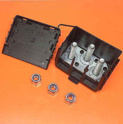
12 / 24V 300A 3 Way / Pin Bus Bar Power Distribution Box Cable Connector Block | eBay UK
1 x 12/24V 300A 3 Way Power Distribution Box Complee with 3 x M8 Stud Bolts. · Max Current – 300A Peak. Genuine MTA 12 / 24V 300 AMP 3 Pin / Way Bus Bar Power Junction Connector Box Complete With 3 x M8 Stud Bolts - Automotive & Marine.
www.ebay.co.uk
Connections from any positives go via battery cut off switches and 2 way busbars so I can disconnect easily and instantly (the cut off switches are on the feed out to leisure battery fusebox and feed in from solar panel so I can isolate them quickly)
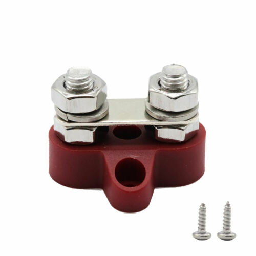
5/16 '' M8 busbar connection block, double insulated | eBay
Find many great new & used options and get the best deals for 5/16 '' M8 busbar connection block, double insulated at the best online prices at eBay! Free delivery for many products.
www.ebay.co.uk
Car Battery Switch Rotary Disconnect Power Cut Off Disconnecter Power Isolator | eBay
Find many great new & used options and get the best deals for Car Battery Switch Rotary Disconnect Power Cut Off Disconnecter Power Isolator at the best online prices at eBay! Free delivery for many products!
www.ebay.co.uk
I think the problem is somewhere in this set up as the problems occur soon as the leisure batteries / DCDC charger are connected to the van via – firstly the cable that is already there under the drivers seat, and secondly when I only had a connection to the pos van batt (12v trigger wasn’t even connected)
WHY – that, is the question.
Ok here are some pics which are a bit shit so I thought I would sketch it out – which also isn’t very good
But here is explanation
I have cross connected 2 x 100Ah lithium batteries in parallel so the supply and feed go into POS on Leisure batt (LB) 1 and the earth is taken from LB2 through 100amp fuse both batt are connected ++ and Neg neg using 100A cable
(Taken from a diagram on net)
Feeds into DCDC charger (under drivers seat)
There is a shunt meter also fitted, main Neg is taken to van earth, 2nd Ned is to the Neg on LB1 and a small pos feed from LB1

.webp")
.webp")
.webp")
.webp")
.webp")
.webp")
.webp")
.webp")
.webp")
.webp")

so you put the neg from DCDC to van earth point and not neg on leisure battery? as Dellmassive says - will it make any diff??
WHY – that, is the question.
Ok here are some pics which are a bit shit so I thought I would sketch it out – which also isn’t very good
But here is explanation
I have cross connected 2 x 100Ah lithium batteries in parallel so the supply and feed go into POS on Leisure batt (LB) 1 and the earth is taken from LB2 through 100amp fuse both batt are connected ++ and Neg neg using 100A cable
(Taken from a diagram on net)
Feeds into DCDC charger (under drivers seat)
- From starter battery to DCDC charger I have used 100A battery wire, at the battery end a 70amp fuse and the charger end a 50amp fuse
- 12v ign wire (from FB in drivers footwell)
- Solar pos input through 20amp fuse (solar neg is taken to earth point on van)
- From the charger to LB1 56A cable fused with 50amp fuse
- Earth to Neg on LB1 56A cable
- Supply feed to fuses and switch panel in van 56A cable fused with 50A through an isolator switch.
- Plus and neg feed to 350w inverter
There is a shunt meter also fitted, main Neg is taken to van earth, 2nd Ned is to the Neg on LB1 and a small pos feed from LB1
Are you on a T6 or 6.1?I fitted a busbar type of thing for connecting all my large cables to (both positive and negatives)
I have a cable from starter battery, cable from leisure battery (via shunt for victron battery monitor), the negative cable from the Redarc DC/DC charger and a cable to one of the earth points under the seat on the negative side (along with anything else that needs an easy accessible earth point)12 / 24V 300A 3 Way / Pin Bus Bar Power Distribution Box Cable Connector Block | eBay UK
1 x 12/24V 300A 3 Way Power Distribution Box Complee with 3 x M8 Stud Bolts. · Max Current – 300A Peak. Genuine MTA 12 / 24V 300 AMP 3 Pin / Way Bus Bar Power Junction Connector Box Complete With 3 x M8 Stud Bolts - Automotive & Marine.www.ebay.co.uk
Connections from any positives go via battery cut off switches and 2 way busbars so I can disconnect easily and instantly (the cut off switches are on the feed out to leisure battery fusebox and feed in from solar panel so I can isolate them quickly)
so you put the neg from DCDC to van earth point and not neg on leisure battery? as Dellmassive says - will it make any diff??
T6, I didn't really need the negative feed from the starter battery through to the DC charger under the passenger seat but I had shotgun battery cable so I figured just run them both together. All negatives connect at the busbar and then to a local earth point under the seat.
Similar threads
- Replies
- 8
- Views
- 964
- Replies
- 4
- Views
- 496
- Replies
- 3
- Views
- 869