Ignition Live Under Passenger Seat - How its done -

This question pops up fairly often so i thought i would look at it a bit closer. . . . .
If your van was factory fitted with the AUX battery under the seat, then your sorted. There is already a feed under there . . . . =]
BUT what if your van hasn't got the Factory option? . . . . Well there are two options for you.
Run (a new wire) the factory wire from the BCM under the dash/steering wheel
or
Run a (a new wire) from the ignition feed center-line of fuses in the under dash fuse panel.
************************************
lets look at the first option #1
The factory setup has a trigger wire that connects the BCM to a relay under the seat, which in tern connects the AUX battery to the front SA fusebox > VW T6 Fusebox - Fusebox/Fuse Chart SA - Primary Battery Fusebox
Now this feed is not an ignition feed as we traditionally know it, it used to be called "X-relief " as its only switched on when the BCM sees a RPM signal from The ECU. So it kicks in and out during start stop events.
this can be seen here:

.
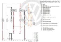
Lets look at the diagram:

download a copy credit: @Loz here> Second battery wiring diagram
You can see that the BCM(J519) has a wire pin in connector T73a /3
its a sw (black) 0.5mm wire core that runs from the BCM under the central cable tunel and up into the seatbase. This is the BCM switched +12v signal when ignition is on and rpm is detected.
This connects to the factory 12v relay (J7) at pin 3, the relay has a perm 0v ground via J7 pin4 (brown wire 1.5mm down to the earth point under the seat base)
If you just needed the ignition feed then thats it . . . . .But if you were fitting an aux battery/relay or DC-DC charger then you need to fit the heavy duty +12v feed cable also.
in the factory setup its a 10mm red cable fed from the SA Fusebox under the starter battery, fed via an 100A supply fuse SA2, REMEMBER you need to fuse BOTH ends of the cable !!! so VW have added a 80A fuse under the seat base to protect the cable from any issues heading back toi the engine bay.
another thing to not is the VW relay is 100A rated.
the factory setup can look like this:

or this:

here is the Factory cable install for the 10mm feed cable . . . . . >
Tpi 2046279, T6 Repair Instructions For Voltage Supply Of 2nd Battery
here is a great guide from @travelvolts Electrics | Travelvolts > https://docs.wixstatic.com/ugd/d959f6_e84b43c19cce424e90952d456c91f103.pdf
and here > Installation Guide for Redarc DC-DC Charging Kit
more info over here > Stop/start...regen...smart Alternator... Dc-dc Charger For Leisure Battery Or Not?
******************************************************************************
So what about option #2 . . . . . well this will give you a more traditional "ignition feed" the BCM supplys the SC fuse box with a +12 supply when the ignition is switched on.
credits to @Loz for these:
here > VW T6 Fusebox - Fusebox/Fuse Chart SC - Lower Dash Fusebox Listings
here > VW T6 Fuse Boxes - Overview Of Fuse Holder Vehicle Locations
here > Fuse Card
you can add new fuse terminals into any blank center fuse holder to addin a new circuits, this is the preferred more professional way of doing it, but dont go crazy with the amps, i would limit the circuits to 5A or 10A (unknown/untested max additional circuit loading to center line SC fuse-box)
you can buy the crimpon fuse terminals from the shop > Four Genuine Volkswagen Crimp Connectors For Stereo Quadlock / Fusebox
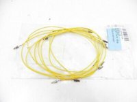
or buy the VW repair wire which comes with a length of yellow wire attached so you can just clip in and join the wire.
like these . . . .

another popular method is the piggyback fuse adapter as seen here>
***********************************************************************
So what about all those existing connectors under the seat . . . . . . one of those must be ignition fed?
NOPE !! see here > Ignition Live Under Passenger Seat
as @Deaky said early on there isnt!
all the mid loom connectors at the bottom, which will be the rear PDC loom, rear lights loom, rear doors loom, rear ABS and brake pad also passenger seat loom,
here:

.

.
***********************************************************************
There is no "No Dedicated Switched Ignition Live Under The Seat" - You Need To Run A New Wire From fuse-box . . . (if you want a separate 12v live when the key is on the accessory position your need a new feed from the center line of the under dash center fuse box.....)
************************************************************************
FYI - (yellow colour plug)
(Green) wire is T17f /9 - G46 Rear left speed sensor (do not connect to this)
(black) wire is T17f /10 - G46 Rear left speed sensor (do not connect to this)
T17f /2 - ABS - (do not connect to this)
T17f /3 - ABS - (do not connect to this)
T17f /8 - F11 Rear right door contact switch - (do not connect to this)
T17f /4 - F10 Rear right door contact switch - (do not connect to this)
T17 /11 - (white) G34 Front left brake pad wear sender - (do not connect to this)
T17 /12 - MX4 Right tail light - (do not connect to this)

.

..
**************************************************************************
There is no "No Dedicated Switched Ignition Live Under The Seat" - You Need To Run A New Wire From fuse-box . . . (if you want a separate 12v live when the key is on the accessory position your need a new feed from the center line of the under dash center fuse box.....)
***************************************************************************
FYI - T17q (black colour plug)
T17q /1 - G203 Rear left parking aid sender (do not connect to this)
T17q /2 - G204 Rear centre left parking aid sender (do not connect to this)
t17q /3 - X68 Positive connection (parking aid), in rear bumper wiring harness (from J446 PDC) (do not connect to this)
t17q /4 - 352 Earth connection (parking aid), in rear bumper wiring harness (from J446 PDC) (do not connect to this)
t17q /5 - G205 Rear centre right parking aid sender (do not connect to this)
t17q /6 - G206 Rear right parking aid sender (do not connect to this)

.
****************************************************************************
more info can be found here:
Installing 12v Socket /s - How Its Done -
.
12v Igntn Feed + 5xusb Charging From Ign Feed - Today's Install
.
12v Aux Feed + 5xusb Charging From Aux Battery - Today's Install
.
Led Rear Interior Lights - How I Done It.
,
Dellmassive`s -- "how I Done It" -- Thread
cant download the VIP docs....? come and jaoin T6F and become a VIP > VIP Membership | VW T6 Forum - The Dedicated VW Transporter T6 Forum
.
work in progress.
T17-P RED conector under seat:
T17p 17-pin connector, red, under seat on front left
1 - wht/grn
2 - or/brn
3 - or/grn
4 - vil
5 - grn
6 - blk/blu - res heat relay
7 - rd/blu -
8 - brn
9 - or/br can?
10 - or/blk can?
11
12 - br/vi - v386
13
14
15
16
17 - rd/yel SC46 - j364 aux heater unit
End.

This question pops up fairly often so i thought i would look at it a bit closer. . . . .
If your van was factory fitted with the AUX battery under the seat, then your sorted. There is already a feed under there . . . . =]
BUT what if your van hasn't got the Factory option? . . . . Well there are two options for you.
Run (a new wire) the factory wire from the BCM under the dash/steering wheel
or
Run a (a new wire) from the ignition feed center-line of fuses in the under dash fuse panel.
************************************
lets look at the first option #1
The factory setup has a trigger wire that connects the BCM to a relay under the seat, which in tern connects the AUX battery to the front SA fusebox > VW T6 Fusebox - Fusebox/Fuse Chart SA - Primary Battery Fusebox
Now this feed is not an ignition feed as we traditionally know it, it used to be called "X-relief " as its only switched on when the BCM sees a RPM signal from The ECU. So it kicks in and out during start stop events.
this can be seen here:
.
Lets look at the diagram:

download a copy credit: @Loz here> Second battery wiring diagram
You can see that the BCM(J519) has a wire pin in connector T73a /3
its a sw (black) 0.5mm wire core that runs from the BCM under the central cable tunel and up into the seatbase. This is the BCM switched +12v signal when ignition is on and rpm is detected.
This connects to the factory 12v relay (J7) at pin 3, the relay has a perm 0v ground via J7 pin4 (brown wire 1.5mm down to the earth point under the seat base)
If you just needed the ignition feed then thats it . . . . .But if you were fitting an aux battery/relay or DC-DC charger then you need to fit the heavy duty +12v feed cable also.
in the factory setup its a 10mm red cable fed from the SA Fusebox under the starter battery, fed via an 100A supply fuse SA2, REMEMBER you need to fuse BOTH ends of the cable !!! so VW have added a 80A fuse under the seat base to protect the cable from any issues heading back toi the engine bay.
another thing to not is the VW relay is 100A rated.
the factory setup can look like this:
or this:
here is the Factory cable install for the 10mm feed cable . . . . . >
Tpi 2046279, T6 Repair Instructions For Voltage Supply Of 2nd Battery
here is a great guide from @travelvolts Electrics | Travelvolts > https://docs.wixstatic.com/ugd/d959f6_e84b43c19cce424e90952d456c91f103.pdf
and here > Installation Guide for Redarc DC-DC Charging Kit
more info over here > Stop/start...regen...smart Alternator... Dc-dc Charger For Leisure Battery Or Not?
******************************************************************************
So what about option #2 . . . . . well this will give you a more traditional "ignition feed" the BCM supplys the SC fuse box with a +12 supply when the ignition is switched on.
credits to @Loz for these:
here > VW T6 Fusebox - Fusebox/Fuse Chart SC - Lower Dash Fusebox Listings
here > VW T6 Fuse Boxes - Overview Of Fuse Holder Vehicle Locations
here > Fuse Card
you can add new fuse terminals into any blank center fuse holder to addin a new circuits, this is the preferred more professional way of doing it, but dont go crazy with the amps, i would limit the circuits to 5A or 10A (unknown/untested max additional circuit loading to center line SC fuse-box)
you can buy the crimpon fuse terminals from the shop > Four Genuine Volkswagen Crimp Connectors For Stereo Quadlock / Fusebox
or buy the VW repair wire which comes with a length of yellow wire attached so you can just clip in and join the wire.
like these . . . .

another popular method is the piggyback fuse adapter as seen here>
***********************************************************************
So what about all those existing connectors under the seat . . . . . . one of those must be ignition fed?
NOPE !! see here > Ignition Live Under Passenger Seat
as @Deaky said early on there isnt!
all the mid loom connectors at the bottom, which will be the rear PDC loom, rear lights loom, rear doors loom, rear ABS and brake pad also passenger seat loom,
here:
.
.
***********************************************************************
There is no "No Dedicated Switched Ignition Live Under The Seat" - You Need To Run A New Wire From fuse-box . . . (if you want a separate 12v live when the key is on the accessory position your need a new feed from the center line of the under dash center fuse box.....)
************************************************************************
FYI - (yellow colour plug)
(Green) wire is T17f /9 - G46 Rear left speed sensor (do not connect to this)
(black) wire is T17f /10 - G46 Rear left speed sensor (do not connect to this)
T17f /2 - ABS - (do not connect to this)
T17f /3 - ABS - (do not connect to this)
T17f /8 - F11 Rear right door contact switch - (do not connect to this)
T17f /4 - F10 Rear right door contact switch - (do not connect to this)
T17 /11 - (white) G34 Front left brake pad wear sender - (do not connect to this)
T17 /12 - MX4 Right tail light - (do not connect to this)
.
..
**************************************************************************
There is no "No Dedicated Switched Ignition Live Under The Seat" - You Need To Run A New Wire From fuse-box . . . (if you want a separate 12v live when the key is on the accessory position your need a new feed from the center line of the under dash center fuse box.....)
***************************************************************************
FYI - T17q (black colour plug)
T17q /1 - G203 Rear left parking aid sender (do not connect to this)
T17q /2 - G204 Rear centre left parking aid sender (do not connect to this)
t17q /3 - X68 Positive connection (parking aid), in rear bumper wiring harness (from J446 PDC) (do not connect to this)
t17q /4 - 352 Earth connection (parking aid), in rear bumper wiring harness (from J446 PDC) (do not connect to this)
t17q /5 - G205 Rear centre right parking aid sender (do not connect to this)
t17q /6 - G206 Rear right parking aid sender (do not connect to this)
.
****************************************************************************
more info can be found here:
Installing 12v Socket /s - How Its Done -
.
12v Igntn Feed + 5xusb Charging From Ign Feed - Today's Install
.
12v Aux Feed + 5xusb Charging From Aux Battery - Today's Install
.
Led Rear Interior Lights - How I Done It.
,
Dellmassive`s -- "how I Done It" -- Thread
cant download the VIP docs....? come and jaoin T6F and become a VIP > VIP Membership | VW T6 Forum - The Dedicated VW Transporter T6 Forum
.
work in progress.
T17-P RED conector under seat:
T17p 17-pin connector, red, under seat on front left
1 - wht/grn
2 - or/brn
3 - or/grn
4 - vil
5 - grn
6 - blk/blu - res heat relay
7 - rd/blu -
8 - brn
9 - or/br can?
10 - or/blk can?
11
12 - br/vi - v386
13
14
15
16
17 - rd/yel SC46 - j364 aux heater unit
End.
Last edited:
