Ignition Live Under Passenger Seat - How Its Done -

I'm working on a T6.1 Transporter with second battery. IS2 if option codes mean anything to anyone.
If I'm reading correctly - the IS2 is the game changer. The engine running signal for OEM second battery isolation relay comes from "J608-Special vehicle control unit". Wiring diagram No.69/5, 805/15. But, the relay J7 is still be there...

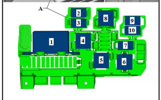
EDIT: Battery isolation relay J7 - below #1 - under left seat.
1652079772732.png
 
Cheers for all the responses.

I'm working with a T6.1 with OEM second battery and control module for external use.

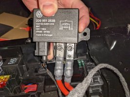
PXL_20220504_044635816.jpg
You can see the signal wires on the left.

I've used these OEM feeds to go in and out of the charger and followed @Loz travelvolts instructions to a T.

I intended to use the black wire seen in this pic as the signal but that is the one that has been giving me the reading on the multimeter when the van is switched off.

Feel free to tell me I'm being silly. Have they changed it so the lack of voltage is what closes the relay? Or am I looking at it wrong?
 
Just a thought but did you just turn ignition off or also remove key from barrel?

I was just thinking special vehicle control module might make it actual ignition live as opposed to engine run signal
 
Ohh nice....

VW have move over to a Citrix style relay..... Very nice.

.much better, and will be able to handle much more current with those bolted connections compaired to the older plug in relay.

.

Once we get this sorted itt update the OP with T6.1 specific info.
 
Thanks for your help all. I took some of your suggestions to investigate what was going on. Here's some info.

The Van
T6.1 Transporter Van LWB TDI450 7spd DSG 4Motion. Production date April 2021.

Lots of factory fitted options but the ones relevant to this convo are:
-2nd battery (75 Ah, AGM) with cut-off relay and battery monitoring
-Stronger battery and stronger alternator

My intention was to upgrade the OEM split relay system (which @Dellmassive has suggested is a new version) and setting up my REDARC BCDC1225D

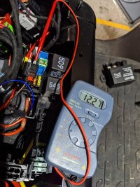
After the funny behaviour I explained I investigated what was going on at the signal cable with the multimeter. PXL_20220510_001511258.jpgPXL_20220510_001637247.jpg
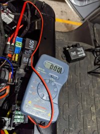
This is the sequence or testing and results:
-Test after engine off over night: No Signal
-Test with ignition on: No Signal
-Test with engine running: + Signal
-Test with engine off again: No Signal
Phew. Everything seems to be behaving.... But then...
-Unexpected + Signal about 1 min after engine off.
-No Signal again a few minutes later....

I'm not going to try deduce exactly what is going on here because I dont think this is accurate or enough data. What I can say though is the signal is a bit more complex than just + when engine RPM. It's not ideal as if it's +Signal, even if just for a bit after engine off the DC-DC system will draw from the starter battery after turning off the car. So what am I going to do?

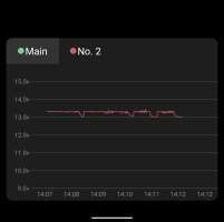
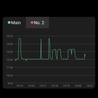
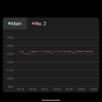
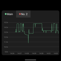
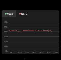
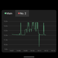
I'm going to keep running the system and see how it behaves over a period of time. I've added below some probably familiar looking voltage graphs of my two batteries on a drive I took today with the new DC-DC charger running. If you look closely it seems to be doing what I hoped it would.
-It's charging from the starter battery when the alternator isn't running
-It's charging from the Alternator when it's it's running at low power
-It's charging from the Alternator when it's running at full power or during regen breaking
It's NOT charging when the engine is off (start stop)

Make of this info what you will. I'll post again if anything goes badly or if I have to change it.
Screenshot_20220511-141231~2.png
Screenshot_20220511-141241~2.png
Screenshot_20220511-142110~2.pngScreenshot_20220511-142128~2.pngScreenshot_20220511-143254~2.pngScreenshot_20220511-143303~2.png
 
@EquanimousMike

That unexpected signal after ignition off is really weird - I have no idea what's going on.

But maybe it's not the end of the world, after all your dc-dc charger will limit the maximum current taken from the main battery. And that maximum current would be only be realized if the secondary battery would be quite empty. Also if the weird signal is consistently on only for a shortish period of time the maximum Ah secondary battery can ever draw from starter is also limited and known in advance.

If this keeps bugging you measure the ignition live behaviour from the fuse box - you always have the option of running the separate wire from a piggy back fuse there. I think you find that taken from the fuse box secondary battery charging will stay on during start/stop, which is perhaps not so desirable, but it would be interesting to know if that signal also does the weird bump after ignition off.
 
That unexpected signal after ignition off is really weird - I have no idea what's going on.

But maybe it's not the end of the world, ...
Completely agree with all of this. I think the only reason it's going to bug me is because of my curiosity. I'm confident the starter battery is safe. I might try dive deeper to see what cleverness the BCM is up to.

Happy with the set up so far though and It's ready to have a solar blanket plugged into it to meet all my needs.
 
The signal going to the relay is not an equivalent to the BCM engine running signal.

It is a relay control signal.

The logic to control the relay will be doing things like disconnecting the second battery during engine start, connecting the batteries together to measure the relative charge state by looking at the shunts on both batteries when they are connected together with no charge voltage present.

There will almost certainly be some logic which attempts to balance the two batteries, and the relay, in conjunction with the shunts, will be used to control charging of the starter and second battery.

IMO, use the BCM engine run signal if you want to know if the engine is running. I am currently struggling with the same issue in my Ocean where the second and third battery are connected by the relay controlled by the Special Vehicle Control Unit ... the Ocean also has two charging sources on both sides of the relay, so the relay is closed when connected to 240V to allow the charger to charge the starter battery. This makes the use of DC-DC chargers for Lithium batteries very challenging.

If I were to have my time again, I would go for a base Transporter with no VW second or third battery and add the leisure electrical system myself. While the Camper Module and the completely integrated OEM system is quite nice to use, modifications are certainly not straightforward.
 
The signal going to the relay is not an equivalent to the BCM engine running signal.

It is a relay control signal.

The logic to control the relay will be doing things like disconnecting the second battery during engine start, connecting the batteries together to measure the relative charge state by looking at the shunts on both batteries when they are connected together with no charge voltage present.

There will almost certainly be some logic which attempts to balance the two batteries, and the relay, in conjunction with the shunts, will be used to control charging of the starter and second battery.
If that relay control signal is activated during ign-off for limited periods only, then adding an activation delay may be the easy way out. (Victron Smart-series DCDC converters have a configurable activation delay) Anyone studied the signal and can tell about durations of the activation periods please?
 
If that relay control signal is activated during ign-off for limited periods only, then adding an activation delay may be the easy way out. (Victron Smart-series DCDC converters have a configurable activation delay) Anyone studied the signal and can tell about durations of the activation periods please?
It's activated during ignition off when the external 220V is connected to shore power - the on-board VW battery charger then charges all batteries. I haven't seen it switched on in any other situation when ignition is off ... I may be wrong but it makes sense from an energy perspective as when the engine isn't running and there is no external 220V then connecting the batteries together allows the camper equipment to discharge the starter battery, potentially preventing an engine start.
 
[Option #2] Run a (new) wire from the ignition feed center-line of fuses in the under dash fuse panel.
Can anybody recommend the best and/or easiest cable route to run from this fuse panel to under the passenger seat? I assume seats and floor will need removing?
 
Can anybody recommend the best and/or easiest cable route to run from this fuse panel to under the passenger seat? I assume seats and floor will need removing?
Yes, removing the seats and lifting one side or or all of the floor mat isn’t too difficult. About 3/10 on the T6 Forum difficulty scale.
When you get there you will see the factory looms running in channels on the floor.
Should be straight forward to run what you need in. I think there are some photos of the floor there on my build thread. Link in signature. :)
 
Apologies for the thread necromancy if that's not the done thing on this forum...

Is this still true (and I fear it is) if you have a factory fit towbar - because in my naivety I had assumed that because a 13 pin towbar should switch pin 10 on with the engine running I could use that to provide a suitable feed to run a fridge in the van or provide a socket to charge my smaller lithium power pack. As I will only ever tow basic trailers and 30A would be more than fine for what I need, it seemed like a plan.

I now fear that the van (MY21 T6.1 Caravelle) is being too clever and is only going to put this line live when engine is running and a trailer is detected through the lighting pins in the 13 pin towbar socket. And that is done by a relay embedded in the trailer control module (as I don't see any external relay in the wiring diagram). So it's sort of true, but only when you have a trailer plugged in.

It's just so nearly there...
Have you tested the pin 10 output with a trailer plugged in? I have the factory towbar on my t6 & pin 10 had to be enabled via VCDS. It wasn’t activated by default in the factory.
 
Not yet, I've been going through the wiring diagrams and comparing them to the fuses and relays I have.

I know the basics work as I've tested a trailer light board, but that's via 13 to 7 converter.

I also want to see if I can charge via the 13 pin socket, which is the other reason I've been looking, so a 13 pin plug arriving this weekend and I will do some very careful testing - at least I now know where the 4x30A fuses are even if it's a mystery as to which does what pins as that's all in the black box trailer module...
 
Nice,

assuming you have a T6.1 with the trailer electrics module. and the green U10 connector under the seat.

This thread was started as a T6 guide . . . but its good to start adding in T6.1 specific stuff.
Is this definitely unique to a T6.1 then? What does the T6 use for trailer modules then? Is it a different scenario entirely?
 
Is this definitely unique to a T6.1 then? What does the T6 use for trailer modules then? Is it a different scenario entirely?
Not sure. I haven't got OEM trailer stuff on our vans.

But the T6.1 is very, different than the T6.... Electrically speaking.
 
Back
Top