[Guide] How To Retrofit MFSW And Cruise Control To T6 Eu6 2019 Startline - Also Hacking DSG Paddles For CCS

Seems an odd one, can you give us some more info please?
Have you done the other coding shown in post #4?
Which buttons now work the horn?
What vehicle is the MFSW from?
What vehicle is the MFSW loom from and has it been modified?
VCDS can show you which buttons are being activated.
 
Seems an odd one, can you give us some more info please?
Have you done the other coding shown in post #4?
Which buttons now work the horn?
What vehicle is the MFSW from?
What vehicle is the MFSW loom from and has it been modified?
VCDS can show you which buttons are being activated.

2019 T6 startline van, (basic plastic wheel and non cruise)
Leather Steering wheel and controls from a 2017 T6 Highline 7E0959442 (non acc)
Original steering wheel loom used adding kufatec add in loom for controls, horn wire removed wires added to terminal 8,9 and 10 (as per instructions).
Column connector Pin 9, run to light switch pin 4
Pin 10, run to Pin 36 on Bcm
Pin 11, run to E-boxIMG_2899.JPGIMG_2898.JPGIMG_2897.JPGIMG_2899.JPGIMG_2898.JPGIMG_2897.JPGIMG_2896.JPGIMG_2894.JPGIMG_2893.JPG
coding:
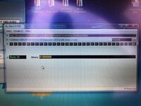
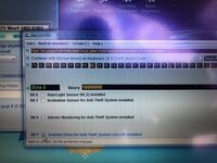
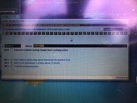
ecu (01)- byte 5 bit 5 - done
BCM (09)- byte 9 bit 3 - done
- byte 15 bit 0 - done
- byte 17 bit 7 - done
- byte 17 bit 2 - done
- byte 29 bit 6 - done
infotainment (5F) - Car_Function_list_CAN_Gen2 MFL set to available
- MFL MSG bus set to Terminal 15

everything work except the horn
 
The coding screenshots are out of focus so assuming they are ok, I would double check the MFSW harness that you have modified.
Also I don't know what "MFL MSG bus set to Terminal 15" is for.
Which buttons work the horn?
Do all the buttons work as they should even if one/some/all the buttons work the horn as well?

Clicked on photos so now can see them clearly. Why have you altered Byte 8?
Mine is 92 which might be worth trying as a test to see if it gets the horn working.
Post #52 shows my BCM coding and is also a 2019 startline.
 
Last edited:
The coding screenshots are out of focus so assuming they are ok, I would double check the MFSW harness that you have modified.
Also I don't know what "MFL MSG bus set to Terminal 15" is for.
Which buttons work the horn?
Do all the buttons work as they should even if one/some/all the buttons work the horn as well?

Clicked on photos so now can see them clearly. Why have you altered Byte 8?
Mine is 92 which might be worth trying as a test to see if it gets the horn working.
Post #52 shows my BCM coding and is also a 2019 startline.

Thankyou for your time.
The horn does not operate with any buttons.
I was trying byte 8 just to see if it made a difference but it did not so i reverted it back.
I have re-checked the steering wheel loom and all seems correct according to the instructions, hence why i am at a loss
 
I understand the problem now, when you said you activated the horn with VCDS I thought you then pushed a button and it worked. As the coding seems OK and the buttons are working, I suspect it is a wiring problem.
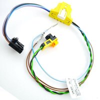
Here is a photo of my loom -


s-l1600.jpg

It is for a Polo (part number 6RD 971 584 D) and I had to change one of the horn spade terminals as it was the wrong size. Do you have all 5 wires going to the black connector - especially the blue/white wire? Hard to tell but looking at the photo the order is brown, black, purple/white, blue/white then grey. The blue/white wire when connected to the brown wire should sound the horn. Try this (by touching the spade terminals together) incase the horn switch is not making properly. Check continuity from the spade terminals to the black connector terminals. Also use VCDS to see if it shows the horn switch signal change. As Mocko1962 said above, some photos of the loom and the instructions would be usefull.
 
Last edited:
I understand the problem now, when you said you activated the horn with VCDS I thought you then pushed a button and it worked. As the coding seems OK and the buttons are working, I suspect it is a wiring problem.
Here is a photo of my loom -


View attachment 73093

It is for a Polo (part number 6RD 971 584 D) and I had to change one of the horn spade terminals as it was the wrong size. Do you have all 5 wires going to the black connector - especially the blue/white wire? Hard to tell but looking at the photo the order is brown, black, purple/white, blue/white then grey. The blue/white wire when connected to the brown wire should sound the horn. Try this (by touching the spade terminals together) incase the horn switch is not making properly. Check continuity from the spade terminals to the black connector terminals. Also use VCDS to see if it shows the horn switch signal change. As Mocko1962 said above, some photos of the loom and the instructions would be usefull.

Here we go , i will try to explain the best i can :)
( metering across airbag horn contacts show contacts ok when pressed)
Pics won't really help as its all taped up and all wires white


This is the loom used, all wires white with labels. added to original loom.
(Original Blue/white wire removed both ends Spade one end pin 8 of clock spring the other end)

New loom:
clock spring join wire, pin 7 (brown ) - join wire that goes to pin 1 on black connector
clock spring add wire, pin 8 (removed blue/white) - pin 5 black connector
clock spring add wire pin 09 - goes to pin 3 black connector
clock spring add wire pin 10 - goes to pin 2 black connector
black connector pin 4 - (spade terminal) goes to where blue/white was removed

If I touch the spade terminal together nothing,
i do have all 5 wires in the black connector.
I can't find the measuring block for the horn switch only an out put test.
At then clock spring the instructions link pin 7 (brown wire), Via the left hand switch
and pin 8 horn (Blue/white), if i touch these nothing.

Anybody got a pic of the inside of their clock spring plug with coloured wires as above?
 
Concentrating on the 2 horn wires - brown and blue/white with spade terminals in my photo - do they have continuity with the black connector pins 1 and 4 respectively?
 
As this was proving a headache, I have just had my friend round with a 2016 polo. I swapped the steering wheel over and the horn works :) , the steering wheel i bought has faulty switch gear :(. Problem found thanks for the help
 
That's good. In post #68 you said the contacts are ok and in post #70 you said it did link pins 1 and 4 - so maybe something like the loom is stopping the airbag being pressed in enough for the switch when the airbag is clipped in.
 
Last edited:
Just thought I’d add on to this post, if I have a 2018 polo mfsw wheel (none cruise) and have run the wire to the light switch and bcm, do I use this loom ? It’s a polo loom, but 4 wires in the the steering wheel clip. The van is a t6 startline with basic none mfsw. Thanks for any guidance

A8ECA619-9B0E-47A4-822B-E2F86F94DAEE.png
 
That's good. In post #68 you said the contacts are ok and in post #70 you said it did link pins 1 and 4 - so maybe something like the loom is stopping the airbag being pressed in enough for the switch when the airbag is clipped in.
I used the same loom in both steering wheels, the polo works the t6 doesn't. As pins 1 and 4 go into the left switch what ever the issue is, is in there. I will pull it apart and have a look but its probably a resistor or something along those lines i will not be able to fix.
Thanks for all the help
 
Just thought I’d add on to this post, if I have a 2018 polo mfsw wheel (none cruise) and have run the wire to the light switch and bcm, do I use this loom ? It’s a polo loom, but 4 wires in the the steering wheel clip. The van is a t6 startline with basic none mfsw. Thanks for any guidance

View attachment 73234
I am may be wrong but I think you need all 5 wires in the black plug. That maybe a loom from a pol that doesn't have both sets of controls
 
Hard to see from the photo but it looks like the blue/white horn wire that is missing from pin 4 of the black connector. If so it should work for a non cruise wheel.
 
I used the same loom in both steering wheels, the polo works the t6 doesn't. As pins 1 and 4 go into the left switch what ever the issue is, is in there. I will pull it apart and have a look but its probably a resistor or something along those lines i will not be able to fix.
Thanks for all the help

Could be a pain to sort that out. If you look through the paddles mod section it shows you how to get at the pcb and some photos of it.
 
So I fitted and coded and works ok.
Buttons not working are the up/down arrows on the RHS, OK button and Voice button.
 
Back
Top