[Guide] How To Retrofit MFSW And Cruise Control To T6 Eu6 2019 Startline - Also Hacking DSG Paddles For CCS

chang1

Member
T6 Pro
Disclaimer - use this information at your own peril - I may have got things wrong.

I am hoping this "how to" will be a one stop place for all the information, owners of poverty spec, 2019, EU6, T6's need, to fit a multi function steering wheel (MFSW) and to enable the cruise control system (CCS). I have also list the coding needed. Most of this can be found in various threads on here and I thank all the contributors for all the time they have put in to enable us to do this especially -
Dnoermann, Pauly, Deaky, Loz and Dellmassive.
The problem is, the information is fragmented and gets confused with T5s and T6 EU5 vans which tripped me up more than once.

There are 6 sections -

1 - Introduction

2 - Selection of parts

3 - Fitting and Wiring up the Parts

4 - Coding to get it all working

5 - Problems Encountered

6 - Not for the squeamish - how to modify DSG flappy paddles to work the CCS "Set" and "Resume" functions which also increase or reduce speed by 1 MPH at a time.

Introduction (skip this ramble if you only want the guide)

My van is a company van that will be returned (as standard) in about 3 years so there was no point me spending much on this project. We only get the most basic poverty spec vans but this one actually has most of the kit I have been yearning for, for many years. The days of trying to wind down the passenger window on a hot summer day are at last gone. Electric windows + mirrors, air con, and now even reversing sensors but still no CCS. It is a £150 inc. VAT option on a £22000 van for crying out loud. I just missed out on a T6.1 that has CCS and an MFSW as standard. Then I thought "if they won't even let me have the chance to pay for it , I will cobble something together myself". Thus started my quest for a cheap CCS. My friend Ebay came up with a brand new, genuine VW CCS kit costing £133 (from vwdirect) that consisted of new stalks and a wiring loom with instructions. I then entered the world of coding, after a lot of research, I decided VCDS or VCP were my 2 choices that could do the job and diagnose any other problems I may cause or encounter. Even second hand they were way out of my budget so I went to the darkside and bought a clone of an old VCP (5.5.1) on Ebay for £20. I fitted the stalks and wired them up and then came the dangerous part of the job. With a nervous sweat on, I tried the VCP. The magic smoke was still contained but I could not get the BCM to accept my code so stopped before any damage could be done. A month later the £30 Aliexpress VCDS new style Hex V2 (19.6.0) arrived and despite my worst fears the BCM and instruments actually accepted the codes without any drama. However my joy was short lived as the ECU would not accept its code and just gave me error 30 no matter what I did - bonnet open, door open ignition on, engine running - nothing worked. Those cunning boffins at VW had introduced some barrier on this new van that no-one that I could find, online, had bypassed. So close, I was one bit away from CCS heaven. After a week or two I decided to give the VCP another shot and success, it coded the missing bit first try. Time for a test drive but no icon appeared on the display. A bit of diagnosing found no signals from the buttons which I quickly traced to a wrongly inserted fuse in the +12v wire I had fitted. At last all working fine apart from a CCS fault now and then that cleared with a key cycle. A few months later and I was still loving my CCS but wanted more - adaptive cruise control (ACC) was the new holy grail. So the research started again. I soon found that despite having all the kit needed, apart from the MFSW, that the VW boffins had made it an impossible dream - at this time. But after seeing all those lovely MFSW's, I wanted one and they seemed so easy to fit, in fact easier than changing the stalks but far more expensive. The hunt was on and Ebay came up trumps - a brand new leather MFSW for a T6 costing £130 but it had flappy paddles. I new it had the correct buttons but how would the paddles affect things. I took the gamble and after being told the wheel is scratched and I can have 30 Euros off the price, I paid the Lithuanian Ebay seller (600ene). It arrived a week later in a box that had almost lost its precious contents through a completely ripped edge of the box. Despite that the wheel was almost perfect so I definitely recommend him if you need a genuine wheel at a bargain price. I had already ordered an £11 MFSW harness from Aliexpress that arrived about the same time but it was the wrong type, so £30 and a couple of days later I had a suitable harness, done the button hack and armed with the right parts and was ready for the install. As to be expected things did not go smoothly but in the end I got it all working, even with the modifications which are a great improvement.
 
Selecting the Parts Needed


1 - MFSW


A T6 or polo wheel is the most likely to be a compatible fit. make sure it has the CNL button and not the mode button and definitely no ACC button in the middle. Anything else is probably going to need modifying. I have not seen it done, but I have been wondering if changing the code in the buttons (BCM subsystem) could get these other buttons to work. It seems odd to me that VW would use differently programmed pic chips in the buttons when changing bits in the coding would allow the selection of what type of buttons are present. Otherwise the only option is to swap the pic chip with a compatible one. Golf wheels may look nice but if you cannot get the correct buttons to fit then expect pain. Also to consider is the buttons are lit up red on T6s and Polos whereas Golfs are white. If you have a DSG then flappy paddles would also be nice and simple upgrade but for a manual they are not used but OK to fit (with an extra bit of coding).

Section 6 has some information on how to remove the buttons if needed and coding for the flappy paddles.


Button part numbers

Without CCS/ACC: 2H0959442
CCS Buttons: 7E0959442 - The one you want but others may work.
ACC buttons: 7E0959442A - untested but may work with coding


Also make sure you have the correct wheel for your airbag (or visa-versa). The standard airbag is held in place by 2 hooks so make sure your wheel has these if you want to reuse your air bag.


2 - MFSW Harness


This connects the clock spring to the air bag and buttons. There are many types so take a look at what air bag and button connectors you have before ordering. I used one for a Polo (part number 6RD 971 584 D ) which I had to change one of the spade connectors for the horn. Check the black button connector is the same and it has all 5 wires as well as the actual air bag connector is correct.


3 - Air Bag


These are expensive and you may not be popular with your postman if you need it delivered. I went for a wheel that could house the same air bag which saved a lot of money.


4 - Repair Wires


You will need to install 3 wires that have the correct terminals to fit the various connectors. They were in my CCS kit so don't know who supplies them - maybe TPS.


5 - Stalks


There is no need to replace the stalks unless the redundant buttons annoy you. If you already have CCS the buttons on the stalk will be disconnected. Both the buttons on the wiper stalk and the new MFSW for the display will still work but the first one used after starting will disable the other until the next start.


6 - Coding Device


I cheaped out with my dodgy Chinese clones which I would not recommend due to the risks involved but they did do the job for me between them. If you are keeping any VW for a while then go for the originals if possible. VCDS is a great piece of kit and more than capable of doing the job. Carista and OBD Eleven may also do the required coding at a much cheaper price but I have not used them at all.
 
Fitting and Wiring up the Parts


Before you do anything, get your coding tool of choice and do a full systems scan (VCDS auto scan) and save it. This could make future trouble shooting so much easier. Also it is worthwhile checking out and clearing any faults and after a short drive do another scan to make sure any important faults have gone.


1 - Remove the Steering Wheel


Disconnect the battery (remember you will not be able to open the tailgate to get at your tools) and allow 10 mins for any power to discharge.

Separate the top part of the plastic around the column and fold it back against the clocks.

Undo the 2 bolts behind the wheel and the one by the height adjuster then remove the bottom section.

Turn the wheel to 3 Oclock and lower it.

Use a small flat bladed screwdriver to slide the air bag retainers towards the centre of the wheel (a small mirror or camera phone may help)

Turn the wheel 180 degrees and do the other side.

Centre the wheel.

Pull the air bag out a bit and pull the connectors white clip out and squeeze the clip to the connector as you pull the connector from the clock spring.

Undo the M12 spline bolt and after marking its position on the shaft, lift off the wheel.

Try the new wheel for size to give you more enthusiasm for what's to come.


Here is a video but no need to remove the top plastic from the fabric.


2 - Disconnect the Wiring Connector from the Stalks T41


Ensure that the clock spring is not moved by putting some tape on it. There is a small window that shows you when it is centred.

Undo the single bolt holding the stalks clamp.

Pull the stalks towards you a little then pull the connectors retainer up and release the connector, the stalks and clock spring will come off together.


3 - Get Access to the BCM connector


Push in the light switch and turn it to the side light position then pull out the switch and disconnect the connector.

Remove the bolt from within the switch housing and remove the housing - take care with the 2 clips.

The 2 trim panels under the steering column can be unclipped and removed.

Rather than trying to get at the connector from below it is easier from above so next the clocks need removing.

Using trim removers, unclip and remove the air vents either side of the clocks and the clocks surround (watch out for the 5 tiny condoms on the pegs).

Remove the 2 bolts at the bottom of the clocks and unclip the blue connector (I used a small screwdriver to lift the orange retainer) before removing the clocks.

From underneath, reach up above the pedals and find the two connectors on the BCM. The white one nearer to the passenger side is the one you want. Press in the bit stopping the retainer lifting and lift the retainer to remove the connector.

Push the connector up into where the clocks were.

From above, take off the band around the wires and plastic where the wires enter the connector. It can be rolled onto the loom and later rolled back.

Press in the two retainers and slide off the white cover away from the loom.

The black part, with the pins, is in two parts. slide them apart to get at the pins.


Here is a video


And another but for a T5 so only use it to get an idea of what things look like


4 - Get Access to the T10 connector under the battery


If you are lucky and already have CCS then you can skip this otherwise putting the wire into the T10 connector is the hardest part of the installation.

Remove the battery and the covers below it.

There you will find an enormous bunch of wires and connectors along with the ECU. Of course the T10 connector is right at the bottom.

I found the easiest way to get at it was to disconnect all the connector above it first. There are two black connectors so be careful. The one you want should have a black and yellow wire that it connects to the ECU pin 44 with. I also removed the glove box to help with the routing of the wire.


5 - Remove Redundant Wires from the Stalks Connector T41


The horn will now be operated by the LIN Bus so the brown and yellow wire has to be removed from pin 11 and insulated. This stops the horn sounding when the CCS on/off button is pressed.


If you have CCS on the stalks, and are not changing them to non CCS stalks, remove the six stalk CCS wires from pins 26 to 31 and insulate them. Remove the black and yellow CCS wire from pin 45 on the BCM connector T73b.


6 - Install the 3 Repair Wires


First Run two wires from the stalks connector T41 pins 9 and 10 to the pedal area.

If you already have CCS, reuse the black and yellow wire from pin 26 or 29 (they are connected) for pin 11 and another disconnected wire (I used the blue wire from pin 31 don't use the other black and yellow wire) for pin 11 (wires from pins 9 and 11 should now already be installed).

Pin 9 wire needs splicing into the black wire on the light switch connector. Take extra care with this one as if it fails your lights may go out.

Pin 10 wire needs splicing into the wire for pin 36 in the BCM connector T73b

Pin 11 wire goes to pin 1 of the T10 connector under the battery. I routed it through a blanked hole near the wheel arch, that I think would be used for the bonnet release cable on LHD vans. Then I drilled a hole to get to the T10 connector. The loom I had for the old CCS kit just reached the T10 connector.


7 - Put it All Back Together


Reassemble everything by reversing what you did before. Take care with these -

Wires are cable tied and protected where needed.

The clock spring is still centred by checking the window.

The wheels are straight and the new wheel is straight.

The air bag just pushes into place but make sure the wires underneath are not trapped.

The last step is to reconnect the battery.
 
Coding


Now for the fun bit where it all comes to life or not so much fun as very scary if you are using a VCDS clone.


ECU 01:
Set Byte 05, Bit 5 Tells the ECU CCS is fitted

BCM 09:
Set Byte 09, Bit 3 Tells BCM a MFSW is installed
Set Byte 15, Bit 0 Only for a wireless that can use push to talk for mobile phones
Set Byte 17, Bit 2 ?
Set Byte 17, Bit 7 Tells BCM CCS is installed

Set Byte 29, Bit 6 Tells the BCM to use pin 36 on T73b for MFSW LIN Bus
 
Problems Encountered


Finding the right information for a EU6 install amongst all the other variants. I even wired the LIN Bus connection to pin 17 on the BCM which had to be changed to pin 36 - yet another strip down of the dash!

Getting the right MFSW harness.

Coding, my clones did the job but not as well as a genuine VCDS would have.

The stalk CCS kit I used got a +12v from a large wire near the BCM which caused it to give a fault now and then but stopped the CCS completely with the MFSW. When the ignition was turned on the buttons all worked OK but as soon as the engine was started the CCS would show the exclamation mark in the display. The ECU also had an error code - Implausible signal on CCS. On testing I found there was a 3v pulse coming back to the +12v wire when the ignition was turned off. As there was no load on this wire the 3v was not clamped down to ground. Once I moved the wire to the light switch connector black wire all was OK.


Not too many problems but they took many hours to solve.
 
Hacking the Buttons to use Flappy Paddles for the Set and Resume Buttons


The buttons are a bit fiddly to get at and so I wanted to use the paddles as well, especially to increase or reduce the speed setting easily. The 7E0959442 buttons have the connectors for the paddles and just need them coded out to stop fault codes. As you will see the wiring is a little tricky on the buttons pcb.


First the buttons have to be removed. The plastic and aluminium frame just pulls off. Well not quite after a lot of prising and levering and pulling it eventually separates. My pro tip is use a hot air gun to heat the wheel up before starting but it is still tough. Also be careful that the leather does not get pulled up by the ends of the frame. The buttons can now be removed and the CCS buttons taken apart, which I did before turning it on. You will need a penta lobe driver for the security screws or a small flat bladed screwdriver. If only the ACC restrictions were as easy to overcome.

Paddle mods - They are connected with a 3 pin connector a common, a switch signal and a LED supply. The switch has a 7.5k resistor across it, used to sense when the paddles are connected (a fault code is generated in the BCM if they are disconnected. All that is needed is to disassemble the switch and remove the two surface mount resistors and then reassemble.

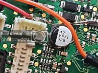
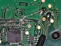
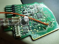
Button Mods - The right hand paddle is wired directly from its connector to the pcb with breadboard patch wires. The left hand paddle is still connected to the buttons connector but the connector needs one pin lifting up off the pcb and the track to the centre pin scratched to disconnect it. Both paddles use a single common and one switch wire on each. Thin wires are needed to make the connections, one of which is directly on the pic chip. I broke a track running under the lifted pin so had to put in a link wire. It was a tight squeeze to get it together but not too bad. I messed up which pin mated to which socket and had to swap the outer pins of the paddle connector as I had them the wrong way around (I had lifted the wrong connector pin). I only found this out after finding that the left paddle didn't work when on the van, so had to take it all apart again - more hot air!

Once it is all together and on the van all that is needed is to code out the paddles to stop the BCM generating missing paddle codes - one for each. To do this you need to go to the BCM in VCDS and then coding and use the drop down menu to select the button subsystem 7E0959442. Long coding is then changed from B1FFFF to B0FFFF if I remember correctly.

All working fine and much easier to set, resume or change speed up or down - 1 MPH per click. All the other buttons are unaffected. The only downside is the paddles don't light up but that's more of a minor decoration than anything so hardly even noticed.
 
Last edited:
Photos

These should have been in the sections above but I missed the 1 hour editing deadline.


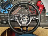
8.jpg
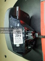
The new MFSW, note the yellow paper dot on the inside, left of the left hook. I think these dots are different on each type of wheel.

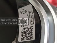
9.jpg
My MFSW label.

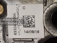
10.jpg
Another label.

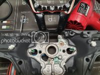
26.jpg
Hooks for air bag.

7.jpg
Buttons connector for MFSW harness.

6.jpg
The new wheel does not line up the same as the old one to keep it straight.

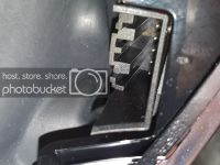
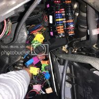
27.jpg
The T10 connector is under here somewhere!

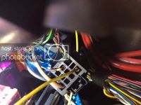
5.jpg
And here it is.

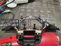
25_1.jpg
The trim, complete with the buttons, removed - eventually! Start at the bottom and work your way up.

11.jpg
One of the paddles.
 
Last edited:
12.jpg[/URL]
The paddle PCB with the two resistors that need removing, the LED can stay.

24_2.jpg
Penta lobe screw on the buttons casing.

19.jpg
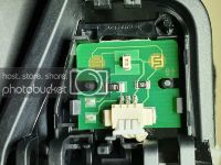
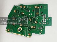
The buttons PCB - how it should look.

20.jpg
The buttons side.

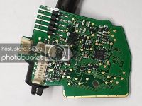
23.jpg
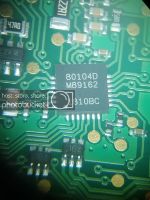
The brains of the buttons - change this if coding does not work.

17.jpg
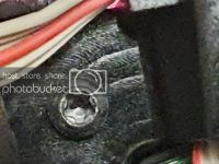
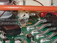
The (wrong) lifted pin (middle under orange wire).

16.jpg
Same from above.

14.jpg
The wire ending at the bottom left is to bridge the damaged track under the lifted pin.

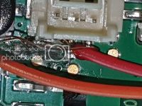
18.jpg
The three important connections that link to the two buttons. I tried leaving the terminal on the right hand wire but it was too big for the case so got cut off.

13.jpg
The finished PCB.
 
Last edited:
Top job putting this together, like you I found there was a lot of information in here, but clouded by contradiction due to van differences. It's good to have all the info in one place so people who wish to do the conversion themselves so they can be directed to this thread in the future as opposed to being told to 'use the search box' or 'call xyz, I paid them $$$ to do mine' that seemed quite common.

I have all the bits to do mine and whilst I think I have all the info I need to install it already, I'll be using this guide.

Again, well done!
 
A simpler way to do the paddle mod, maybe, is to just solder wires to the "3 important connections" (second to last photo) and connect them to the paddle connectors rather than use the buttons socket. Soldering onto the two test pads is easy but the chip leg wire would need a thin wire which then would be joined to a thicker wire. I think that one is the common for the two buttons and the red wire (in the last photo) is the "Res" button, but check first.
The photo of, "One of the paddles", shows the pivot pin partly removed. Once this is out the PCB is easy to get at. A small screwdriver can be used to push it out a little and then a pair of small side cutters can grip it to pull it out. Note which way it is before pulling it out completely.
 
Last edited:
If anyone has fitted an MFSW similar to mine, on a start line van, but with different buttons (such as mode or an ACC button) that doesn't work, can you please try changing the button coding to B0FFFF (or B1FFFF if you have paddles). This may get them working and post here what happened.
 
Last edited:
Just to add some more to this thread from my own experiences having completed a similar task:
  • Steering wheel harness - the off the peg solution is to replace the cable on your old airbag with one with the additional MFSW wires and plug, in addition you need to buy the additional 'repair wires' to connect to the BCM + power etc. I found a different solution to this and that was from a helpful seller from Germany. This kit which came with full instructions, allows you to add the extra wires to your non MFSW airbag harness and was cheaper than the normal airbag harness plus it included the extra cables which are required - Cable Set Multi Function Steering Wheel Loom Buttons Mfl Vw T6 from Yr 4/2015 | eBay
  • I swapped out the stalks (to avoid MFD/cruise control button duplication on the stalks and wheel), which resulted in an ABS fault and stop/start being disabled. I had to complete a steering position sensor calibration generally following this guide to overcome this and clear the fault. i probably should have retained my slipring which would have avoided the need for this but by the time i realised that it was easier re-calibrating!
  • The total cost for me was £79 for the T6 MFSW, £36 for the airbag harness/cables plus an additional £40 for the stalks (which technically wasn't needed, but i wanted the wheel to look like its always been there, i could probably recoup this by selling my old stalks)
To conclude, this mod doesn't need to cost a fortune if you shop about for the parts and wait for a reasonably priced wheel and is well worth the effort!
 
Last edited:
Thanks for a great thread. I am completely confused by this whole thing but its not hard to do that to me. This is the thread I needed to read in the first place.
Ignore my thread now, I went to delete it when I finished reading this one but it would not let me as the delete function dissapears after a while.

I am looking for more of a plug and play standard setup, not wanting to change buttons or airbag wiring as that would make my brain go crazy hoping i dont get it wrong. If there is a loom kit then no problem at all as mentioned in my thread thank you for that. I think I will need both looms by the sounds of it.

I had thought the T6 came with a flat bottom wheel as OEM but this does not seem to be the case in all the adverts I have been looking at to confirm this.
So although I would love a flat bottom, they all seem to have the incorrect buttons or do not take the original airbag.
I am probably in a better position to go for a round wheel designed specifically for a T6 so that I would get the correct buttons in the first place. I then need to add the wiring and do some coding.

The whole point being to add cruise to my shuttle eu6 with no cruise. I have trip so half way there.
BCM from scan is
Address 09: Cent. Elect. (J519) Labels:. 7E0-937-BCM-V1.clb
Part No SW: 7E0 937 090 HW: 7E0 937 090
Component: BCM PQ25 Max4 H80 0736

On the hunt for a standard button T6 wheel. If anyone spots one let me know ;-)
2016 VOLKSWAGEN CARAVELLE T6 MULTIFUNCTION STEERING WHEEL VW 7E0419091 | eBay
 
Finally got this project started,Using the Kufatec instructions and also these instructions I done everything they said.
It told me to put a pin in pin 36 of the BCM connector B however I couldnt as there was already a pin in there and this was not mentioned. So The other option was to splice it in with pin 17 which I done. Mine is a 2016 Shuttle.
The otherside of the fuse I spliced into the ignition feed under the steering column. Black and blue one, thick wire.

Luckily for me I did not have to do the airbag wiring as the wheel I got came with an airbag which was a bonus.

When it came to the coding. This confused me. I done as they said and above but my van would not accept some and/or I did not have anything on the bytes as below.

ECU 01: - It kept telling me the coding was not accepted.
Set Byte 05, Bit 5 Tells the ECU CCS is fitted

BCM 09:
Set Byte 09, Bit 3 Tells BCM a MFSW is installed - done and Sorted
Set Byte 15, Bit 0 Only for a wireless that can use push to talk for mobile phones - How do I know if I have this?
Set Byte 17, Bit 2 ? - nothing there
Set Byte 17, Bit 7 Tells BCM CCS is installed - done and sorted
Set Byte 29, Bit 6 Tells the BCM to use pin 36 on T73b for MFSW LIN Bus - I did not have anything at this byte 29.

Also in this section it told me to change some substr bus but I had no idea what this meant. It said to change to B4FFFF.

The bit below I was told to change also but the stereo worked without doing it so no idea what it does. I have turned it off for the time being.
Then moved to 5f: It said to go into adaptions and change the can gen 2 mfl to available - done this
then can gen 2 mfl bus to terminal 15 - done this

I have the buttons for the stereo working. The bottom buttons volume and the skip left and right buttons. The other right hand buttons seem to do the mfd and phone. The cruise however I am unable to test until I can get out and test drive it after all the no going out is over. Should anything be displayed if it is sat still with the engine running or must you be moving? No left side buttons bring anything up on the dash.
 
Back
Top