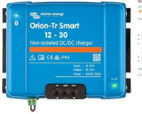
[Guide] DC-DC Charger (for leisure battery) -- How I Done It --

Currently on sale at £161 which seems a cracking deal. I've jumped back to this thread over and over as I'm at the point of electrics. Great write ups and certainly given me a better understanding of what I'm looking for :thumbsup:

 
Currently on sale at £161 which seems a cracking deal. I've jumped back to this thread over and over as I'm at the point of electrics. Great write ups and certainly given me a better understanding of what I'm looking for :thumbsup:

Mine is at the POST Office waiting for me to collect it. I’ll have it tomorrow and let you know how it looks in the flesh. Won’t be installing just yet but will be able to give initial impressions
 
Interesting – it looks like there's second generation models (G2) out, or coming out soon... wonder if anything has changed under the hood?

Screen Shot 2020-10-21 at 17.30.56.png
 
Mine is at the POST Office waiting for me to collect it. I’ll have it tomorrow and let you know how it looks in the flesh. Won’t be installing just yet but will be able to give initial impressions
Yes definitely keep me posted. I ended up ordering myself one this afternoon :p
 
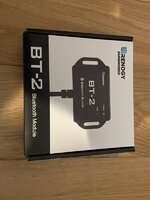
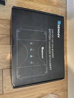
I pickled up my Renogy DCC30S From the post office this morning. First impressions are good. It is well packaged, appears to be well made and comes with all the bits and bobs you’d expect to make installation straightforward. I ordered the optional Bluetooth module with mine.

As it comes in the boxes:
AC634C5F-A369-4968-B807-AC5C44BD37FD.jpeg
05E6D32D-89CE-4D36-943B-07702E761A0B.jpeg

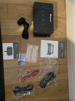
This is what comes in the box:
  • Charger
  • Bluetooth module (seperate option)
  • decent manual (much more in depth that the CTEK one)
  • Ignition wire to connect to a switched IGN feed
  • Temp sensor and cable
  • RS485 cable (for future development connecting to monitoring screen/app)
  • 4 x ring crimp connectors for the main input/output cables
  • some stickers
8352AF97-E328-4C9A-A212-8F1EA8F8141A.jpeg


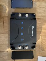
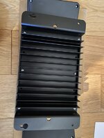
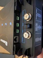
The charger has a neat cover on each end that goes over the main connections to keep them insulated away from debris etc. There is a decent set of fins on the bottom of the unit to distribute the heat and well labelled sockets for plugging in the IGN feed/temp sensor etc.
02067326-C827-4AAA-BD08-967F8AD1224B.jpegA0DBF286-EB33-4CE4-B1F7-70740DFD7744.jpeg03A0C6BC-E873-44D4-94B4-FE79EB696ECD.jpeg

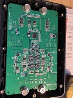
There was no tamperproof screws so i popped the rear cover off to expose the circuit board which looks like this. I didn’t go any further with disassembly.
F015B544-CABC-4D80-9551-9A5AC45DB376.jpeg


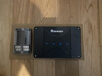
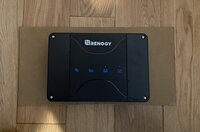
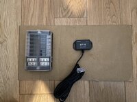
Installation. I’m planning to put mine under the drivers seat to replace the CTEK250SE that is there just now. I also plan to replace my fuse box with a larger unit as I’ll be adding some additional USB outlets and a dedicated feed for my fridge. The Renogy is a fair bit bigger than the CTEK so i was planning to mount it onto a ply board, mounted vertically inside the seat base. I made a cardboard template the same size as the ply board will be and you can see how it might fit in the photos below. It will be quite tight so i may put the Renogy on one side of the board and have it rear facing as I can access it over Bluetooth, then place the Bluetooth module and fuse panel on the front of the board which will be visible from under the front of the drivers seat. The fuse box has an LED next to each feed to show if a fuse is blown so I should be able to see this and change a fuse without taking the seat off.

Renogy and fuse panel on same side of board - no room for Bluetooth module:
7D482E0B-7D6F-48B8-99AB-1B117C6A604C.jpeg

Renogy on one side, fuseboard and Bluetooth Module on the other:
AF7277B7-C7FE-4D44-9ECD-900D8B13AB70.jpegD3CA12D3-0C73-411C-9FBD-5BD05FCEA4DE.jpeg

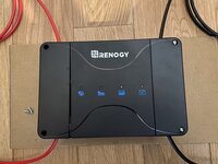
One thing to be aware of is cable entry. The covers mean cables enter as shown below. It should still fit where I plan to put it as there is enough room to make a nice curved entry off of the backboard (Ignore the top right black being in the wrong place this is just to show cable entry)
35AA2A58-85C9-40A0-B5D3-EDE5EED4DEBA.jpeg

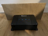
If it were to be placed on the floor under the seat it would look something like shown below. The cardboard template being the same size as the seat base.
CA244F4B-388D-4A49-9FE0-222F05724CD8.jpeg

I won’t be installing it for a few weeks as I have other priorities just now but will post an update when I do install it.
 
Just got the the end of this thread. Now my brain hurts.

I get the impression that if starting the electrics from scratch then the Renergy is the way to go? Especially if you want to put solar on and enable the starter battery to be trickle charged when the leisure battery is at 100%.

Does the victron stuff not have the ability to trickle charge the starter?
Not in one single unit , No.
with Victron you would need multiple units.
1606331318251.png
have look at the new thread i done about maintaining your starter battery . . .
.
(additional carriage returns removed to protect the environment)
 
Last edited by a moderator:
here are some current real-world test results . . . (DEC 2020)
the van has been sat parked for over a week . . so battery wise, not great . . down to 11.9v ish
I grabbed the Victron 12v/15a/1op charger and plugged it into the starter battery hook in point.
View attachment 96764
.
this is the current setup under the bench . . . the 50A Renogy DC-DC / mppt. (the AUX battery is under the drivers seat, an AGM Xtreme 110ah)
View attachment 96765
.
you can see the charger starts up delivering 15A current but rapidly drops and settles at around 10A (@ 14.2v) . . .
View attachment 96766
which starts charging the starter battery . . .
View attachment 96767
....
BUT . . .
because the starter battery voltage rises . . . the Renogy auto VSR kicks in and starts charging the AUX battery . .
which can bee see here in the BMV . . . at 7.4A (( this is the charge current from the starter battery via the DC-DC to the AUX battery))
View attachment 96768
***************
so we are delivering 9.8A from the EHU charger to the starter battery . . .
but 7.4A is going via the DC-DC to the AUX battery.. . . .
if charging the starter was the main concern you can see that the charge power is being split . . . so the starter is not getting the full charge . .
This will carry on until the AUX battery is almost charged (top of absorb cycle) and it starts to draw less current . . . at which point the starter will start to benefit from the full charge power.
**************
This is the BM2 readout from the AUX battery . .
View attachment 96769View attachment 96770
***********
up close on the Renogy you can see the status lights showing ALT power available . . . and charging the AUX battery . . .
View attachment 96771
so you can see that the single charger method works . . . . . but if you have twin low batteries and are drawing a 12v load from your leisure electricals . . . . . dont expect the charger to charge up the starter battery very fast . . . but this works well as a maintainer style charging system.
EDIT:

half-hour later the EHU Victron charger has moved over to float mode . . .
View attachment 96776View attachment 96777
which has dropped the output volts to 13.6 @ 5.7A . . .
View attachment 96779
you can see the drop on the starter BM2 readout.
View attachment 96781View attachment 96782
BUT the BMV shows that the AUX battery is still being charged via the DC-DC . . . ( @ 3.8A )
View attachment 96784
which can be seen here on the AUX BM2 readout . . .
View attachment 96785

(additional carriage returns removed to protect the environment)
 
Last edited by a moderator:
I read this excellent topic on DC-DC charging. But I have a question about an issue you raise early in the topic:

"Now you have a few options: If you have the factory fitted leisure battery or not? If you have the Factory fitted kit then VW will have done all the hard work for you and run all the cables, fitted fuses etc . . . the even give you a nice ignition/engine run wire. (which is nice)"

Having these power and ignition cables in place seems attractive, but since there are two leisure battery options with VW it gets confusing:
8FE AGM with relay and monitoring via IS2/IS7 coupling (requires IS2/IS7 as an extra option)
8FB for a 75AH AGM battery (little less pricey, no mention at all about connection)

How are these VW-factory-kit leisure batteries charged? Isn't there already a convenient DC-DC charger in place?!?!?!
Then if I'd order one of these, which one to choose and why? How are they cabled?
 
@bor im not sure on the T6.1 configuration.

but in the T6 the factory option vas just a relay under the passenger bench - which can be swapped out at a later date for a DC-DC charger.

more info here:


.
 
@bor im not sure on the T6.1 configuration.
but in the T6 the factory option vas just a relay under the passenger bench - which can be swapped out at a later date for a DC-DC charger.

It's like being in a weird club and trying to order a reasonable drink: "I'll have what he is having"
Which is the cheapest way to have under the left seat: AGM battery + fitted mounting bracket + fused power wire + ignition signal. Is 8FB the way to go?

What is your PR-code for the AUX battery: 8FB or 8FE or 8FL?
 
the T6.1 online configurator shows this .

1610988125932.png

..


so the 68ah AGM with cut off relay is the option you want. ( i got a 68ah EFB battery, but as you say i had all the prep work, so battery tray, fused cable, IGN feed etc etc )


..

The second option is for the uprated alternator and slightly largerAGM starter battery. (i have the 180A alternator)


I chose both these options on my original MY18 T6 order.


..


.


heres my PR codes, that dont seem to relate to the extra battery options.


0VF - BTA Information kit in English

8AY - RAO Radio navigation system

7UP - NAV Navigation system MIB2 Standard PQ (EU/ROW)

1Z0 - KRM Initial standard fuel filling

5K0 - LAC Without surface protection, with additional transport protection measures

E0A - AAU No special edition

7RE - CDR SD card (Europe)


RADIO – 8AY

NAVI – 7UP

RESERVED – 1G2 - RER Steel spare wheel with original equipment tire
 
It's like being in a weird club and trying to order a reasonable drink: "I'll have what he is having"
Which is the cheapest way to have under the left seat: AGM battery + fitted mounting bracket + fused power wire + ignition signal. Is 8FB the way to go?

What is your PR-code for the AUX battery: 8FB or 8FE or 8FL?
Perhaps some help in Body builder guidelines: The new Transporter 6.1. chapter 2.5.4.1
 
T6.1 Body-builder-guidelines: VW requires everyone to utilize an isolation relay. This solves the case (presuming this complies to VW-manufacturing as well)

1610989435540.png
 
T6.1 Body-builder-guidelines: VW requires everyone to utilize an isolation relay. This solves the case (presuming this complies to VW-manufacturing as well)

View attachment 99214
yes, thats how the OEM factory fit is done.

fuse and cable from engine fusebox, to seatbase isolation relay,
then 2nd battery with mount tray under seat, with IGN feed for relay.
plus ground connection.

so spec that option./

then when it arrives, just swap out the isolation relay for a decent DC-DC charger.
 
  • Like
Reactions: mmi
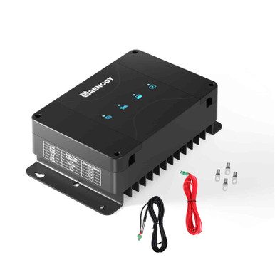
looks like Jon has gone for a Victron Orion DC-DC charger . . . . . . =]

looks like hes gona do i right this time . . . . . . The VSR and Stirling have been sacked. and hes gone Lifepo4 again.


.


.


View attachment 101146
He still won't admit he was wrong the first time. It's concerning that among ths social media "vanlife community" he's regarded as an electrical guru when he always just takes advice from one source and then ignores any critical examination of what he then passes on.
 
Back
Top