They're sent at around 50% SOC as that's the 'storage' charge level. So plenty to check stuff is working!Thought I’d jump on this thread with a question rather than start a whole new thread.,
I’ve just bought the Fogstar eco 100ah
Does anyone know what state of charge they are shipped at?
Haven’t got the charger side of my set up done yet but wanted to check my lights, chargers etc work
Thanks
You are using an out of date browser. It may not display this or other websites correctly.
You should upgrade or use an alternative browser.
You should upgrade or use an alternative browser.
Fogstar Drift 12v 230Ah Seatbase battery -- "How I Done It" --
- Thread starter Dellmassive
- Start date
Around 50%Thought I’d jump on this thread with a question rather than start a whole new thread.,
I’ve just bought the Fogstar eco 100ah
Does anyone know what state of charge they are shipped at?
Haven’t got the charger side of my set up done yet but wanted to check my lights, chargers etc work
Thanks
Hi all,
I've just purchased a Fogstar Drift 230Ah seat base battery and have tried to fit it today. I'm really struggling to fit it beneath the passenger side of my van using a Sportscraft swivel seat base. The seat base is the version supposedly meant to accommodate a battery but to me this seems physically impossible, the battery sits higher than the base frame and the seat base has a strip of metal that fouls on the battery. I've already ground down the earth stud and trimmed back the carpet to try and lower the battery a bit, but this hasn't really made much difference. The only other thing I can think of is perhaps higher the whole base from the floor somehow, is this something anyone has done?
Today has been an extremely frustrating day, wasted loads of time on this getting nowhere.
Any suggestions before I admit defeat?
Thanks,
Mark.
Not tried fitting that battery, but had issues with my Roamer 160. The Sportscraft leisure battery swivel has an extra flat U-brace welded underneath which reduces the available height. People on here remove the underbase earth point and have it sitting on the cab floor to get it low enough. Alternately you can space between seat base and swivel. I made 10mm spacers for a previous AGM battery using threaded Hex on the front and milled spacers and longer bolts on the rear.
Not tried fitting that battery, but had issues with my Roamer 160. The Sportscraft leisure battery swivel has an extra flat U-brace welded underneath which reduces the available height. People on here remove the underbase earth point and have it sitting on the cab floor to get it low enough. Alternately you can space between seat base and swivel. I made 10mm spacers for a previous AGM battery using threaded Hex on the front and milled spacers and longer bolts on the rear.
Thanks for this, glad to see I'm not the only person who has suffered this then! Yes that's exactly the problem, it's the U brace as well as the other angled metal running parallel to the brace that are definitely causing the issues. I did cut down the earth stud to reduce its height but I think the battery is still fouling against this - although I don't believe this will reduce the height enough to make a difference it will certainly help. If I remove the earth stud entirely are there other viable places nearby that I can run the earth wiring under the seat from?
I think realistically the spacer option is the only way this is going to work, 10mm might just about do it. It will make the seat slightly higher but I can't see any other option.
From what I can see the front bolts in the seat base are studs welded in to the base, at present these studs are considerably shorter than required to space the seat plus get a bite from the domed nut atop of the swivel base, how could I reliably extend these studs? The rear seems to be straight forward as I can just use longer bolts with spacers.
Sorry for the stupid questions!
Mark.
Ha ha yes its incredibly tight - so not a daft question at all - just the constraints of making the most of the space available in a Transporter seat base! I haven't fitted that battery, so I recommend seeing what guru @Dellmassive recommends  Someone on the forum will have fixed this issue before
Think people have used one of the seat base bolts with sufficient prep as an earth point.
Yes agreed about the front. I cut down some threaded hex spacers If you want my (redundant) spacers PM me to sort that out, but I would sweat your design bit more to keep the seat lower overall - no idea if there is a solution mind")
Cheers Andy
Someone on the forum will have fixed this issue beforeThink people have used one of the seat base bolts with sufficient prep as an earth point.
Yes agreed about the front. I cut down some threaded hex spacers If you want my (redundant) spacers PM me to sort that out, but I would sweat your design bit more to keep the seat lower overall - no idea if there is a solution mind
Cheers Andy
Last edited:
I have the RIB swivels on mine.
Assume they are similar to the Sports craft.
Got any pictures pics of the battery sitting in the seat base?
I've gone the same with the Roamer sb230, ie cut the earth stud. Trimmed the carpet. The battery JUST fits between the bottom seat rails.
But that battery could on the seat base spacer blocks under the carpet
So you can trim them down.
Or fit spacer shims ,8 or 10mm penny washers ander the swivel plate. Or below the seat base.
More info.
..
Roamer LiFePO4 Gen2 230Ah Seatbase battery -- "How I Done It" --
Its a Lithium LifePo4,
its got massive capacity @ 230Ah,
its got massive discharge performance 250A/500A,
its Bluetooth,
its a Roamer !!,
its exciting . . . . .
its coming soon - the full test . . . . .

 roamer.com

+++++++++++++++
I've managed to get myself a Gen2 230Ah Roamer seatbase battery. - delivery expected Jan 2022.
@Dellmassive
@RoamerBatteries
+++++++++++++++
Its a Lithium LifePo4,
its got massive capacity @ 230Ah,
its got massive discharge performance 250A/500A,
its Bluetooth,
its a Roamer !!,
its exciting . . . . .
its coming soon - the full test . . . . .
Roamer - Premium LiFePO4 Lithium Leisure Batteries Campervans & Boats
"Roamer SMART5, XTREME & HOME: 12V-48V LiFePO4 leisure batteries for campervans, motorhomes & boats. 100Ah-460Ah, Bluetooth BMS, 12-year warranty."
roamer.com
+++++++++++++++
I've managed to get myself a Gen2 230Ah Roamer seatbase battery. - delivery expected Jan 2022.
@Dellmassive
@RoamerBatteries
+++++++++++++++
KEY DETAILS
- Nominal capacity of 230Ah at 12.8V
- Up to...

-- ROAMER 230SB3 (Gen3) --
its finally here, -
the latest Gen3 version of the Roamer - SeatBase 230Ah Lifepo4 battery.
+++
roamer.com
+++
now with a spec and test sheet, QR code for the cell pack. . . stickers and more.

.

.
there is a new sticker on the top with all the important details,
and QR code for the APP,

its the same APP as before. . .

+++

++++++
I've been full testing it over the last few weeks. . .
we built a portable battery...
its finally here, -
the latest Gen3 version of the Roamer - SeatBase 230Ah Lifepo4 battery.
+++
Roamer - Premium LiFePO4 Lithium Leisure Batteries Campervans & Boats
"Roamer SMART5, XTREME & HOME: 12V-48V LiFePO4 leisure batteries for campervans, motorhomes & boats. 100Ah-460Ah, Bluetooth BMS, 12-year warranty."
roamer.com
+++
now with a spec and test sheet, QR code for the cell pack. . . stickers and more.
.
.
there is a new sticker on the top with all the important details,
and QR code for the APP,
its the same APP as before. . .
+++
++++++
I've been full testing it over the last few weeks. . .
we built a portable battery...
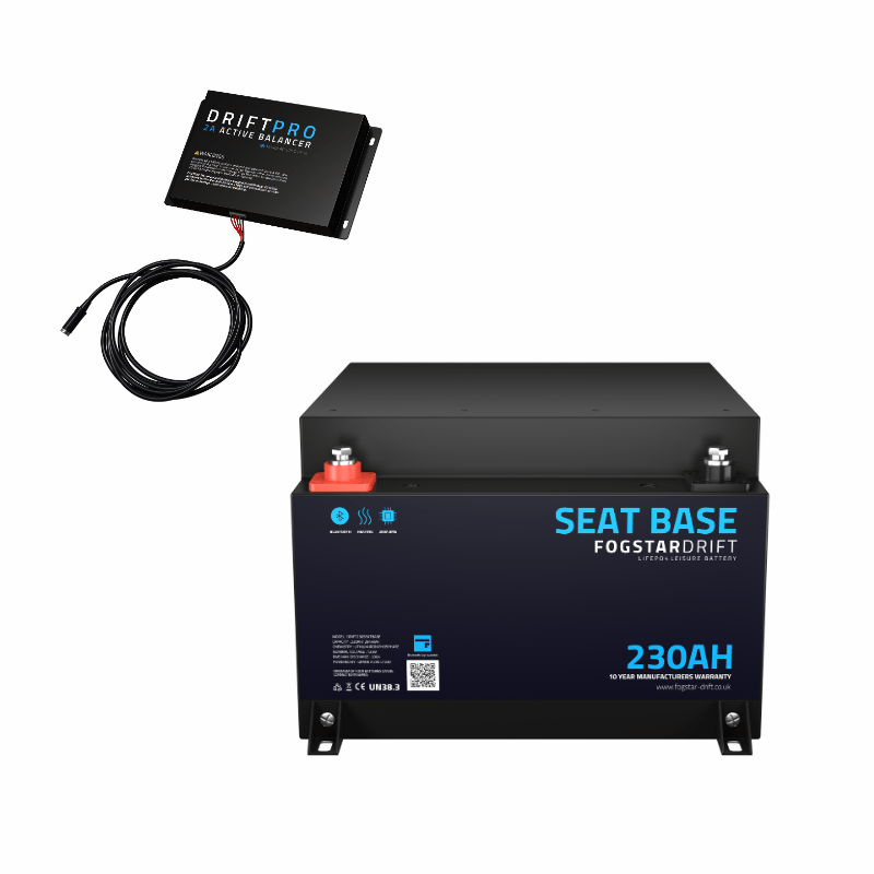
FOGSTAR Drift 12v 230Ah Seatbase battery -- "How I Done It" --
check out the latest @Dellmassive Lifepo4 battery install & test
++++
 www.fogstar.co.uk
++++

yep I've done it again . . . .
and with a wicked BT APP,
Built in HEATER for SubZero Charging,
200A/200A - charge & discharge rates (400A peak)
2944Wh of power
10 years warranty
Active cell balancer (seperate box)
whats not to like.?...
check out the latest @Dellmassive Lifepo4 battery install & test
++++
Seat Base Lithium Leisure Battery - Fogstar Drift 12v 230AhSeat Base 12v 230Ah (with Active Balancer)
Seat Base Lithium Leisure Battery 230ah | Grade A EVE LiFePO4 cells, JBD BMS, Bluetooth & Heating. Just £799.99 with a 10 year warranty.
www.fogstar.co.uk
++++
yep I've done it again . . . .
and with a wicked BT APP,
Built in HEATER for SubZero Charging,
200A/200A - charge & discharge rates (400A peak)
2944Wh of power
10 years warranty
Active cell balancer (seperate box)
whats not to like.?...
- Dellmassive
- dellmassive fogstar how to guide leisure battery
- Replies: 115
- Forum: Electrics, Lighting, ICE, Security
Roamer LiFePO4 Gen4 230Ah Seatbase battery -- "How I Done It" --
++++++
Well, weve known about this New battery for a while now. but had to keep it under wraps,
but its finally here,
and its a game charger !!
Brand New Improved BMS Hardware, with BT & New APP (new APP out soon)
Active 2A cell balancer to keep the cells in check and stop drift,
3600w of power, thats 300A continuous,
230Ah @ 12.8v - 2944Wh,
Low Temp Charge Protection,
Low Voltage Cell protection,
built in Pre-Charge circuit,
Mechanical Sleep Button,
10year warranty,
and the best bit, (the game...
- Dellmassive
- dellmassive how to guide lithium battery roamer seat base
- Replies: 98
- Forum: Electrics, Lighting, ICE, Security

..
So the seat base looks like this:

I'm starting to think this just won't work with the fogstar base battery at all, the protrustions on this swivel base are quite extreme (this is the underneath)
The ridge at the back hits just where the battery terminals are. :-(
I'll get some pictures of the seat base sitting in place later after I get back from work.
Looks like you might have to swap them seat basis for something else?.
I had the RIB ones and it worked fine.
I'm selling a full set of rib seats swivels if you're interested?

 t6forum.com
I had the RIB ones and it worked fine.
I'm selling a full set of rib seats swivels if you're interested?
Sold - RIB seat swivels, Drives side and Passenger side - full kit, no need to adapt hand break
RIB seat swivel kit, Drivers side and Passenger side. +++ 1x RIB VW T5/T6 Single Seat Swivel - Driver (Right Hand Drive) 1x RIB VW T5/T6 Single Seat Swivel - Passenger (Right Hand Drive) +++ no need to adapt hand break with this set, you get two spacer bars to raise above the hand break...
Looks like you might have to swap them seat basis for something else?.
I had the RIB ones and it worked fine.
I'm selling a full set of rib seats swivels if you're interested?
Sold - RIB seat swivels, Drives side and Passenger side - full kit, no need to adapt hand break
RIB seat swivel kit, Drivers side and Passenger side. +++ 1x RIB VW T5/T6 Single Seat Swivel - Driver (Right Hand Drive) 1x RIB VW T5/T6 Single Seat Swivel - Passenger (Right Hand Drive) +++ no need to adapt hand break with this set, you get two spacer bars to raise above the hand break...
Thanks for the offer @Dellmassive but managed to somehow sort this. It was such an incredibly tight squeeze it's a miracle it fit at all. Had to use around 5 penny washers on each seat base stud + 2 penny washers on the seat base. I also had to grind away the ground nut below where the battery sits as you had suggested. For a new ground I sanded away the paint on one of the holes where the seat studs sit to make good electrical contact, then did the same for another hole on the base where I then moved the ground connection too. This seems to have formed a reliable ground based on resistance tests and resolves that issue with a tidy finish.
This incremental addition of spacing was just enough to do the job.
Fogstar have now released the pro series that has victron integration, same as the Roma battery.
Anyone know if these dimensions will fit in a seat base?... We're traveling so not in a position to do any research or have a measure up.
They calling it day 230 amp hour drift pro model. But it's not in the same as the drift non-pro seat base model. (That I have in the van already)
 www.fogstar.co.uk
...
Anyone know if these dimensions will fit in a seat base?... We're traveling so not in a position to do any research or have a measure up.
They calling it day 230 amp hour drift pro model. But it's not in the same as the drift non-pro seat base model. (That I have in the van already)
Drift PRO 12V 230Ah LiFePO4 Leisure BatteryDefault Title
Fogstar Drift PRO 12V 230Ah lithium battery with 2,944Wh capacity, Victron integration, Bluetooth, heating, and 10-year warranty. Ideal for off-grid and vanlife.
www.fogstar.co.uk
...
I like this idea, but just had a thought. Do you think there will be good enough contact for (for example) a current of 300A?My Blue Sea MRBF terminal fuse now fits!
Made up a short busbar out of a piece of solid 3mm thick x 20mm copper bar.
View attachment 247463
Second 230ah going in on the camper.... (Roamer, but basically the same)
400A Mega fuse for now, I'll monitor max load current s and down size fuse accordingly
.


.
400A Mega fuse for now, I'll monitor max load current s and down size fuse accordingly
.
.
Similar threads
- Replies
- 6
- Views
- 639
- Replies
- 16
- Views
- 747
- Replies
- 12
- Views
- 802