[Guide] Clayton LPS II 2500 - 1kWh (leisure battery + Inverter) -- How I Done It --

On mine it just looked like a wire from the Clayton with a piggy back fuse in the fuse box for an ignition feed. Took the fuse out and it stops the ignition feed to the Clayton allowing it to operate freely. I can just put the fuse back in if I want the ignition cutting it off again.
Thanks. That makes sense. I can just unclip the ignition feed cable then.
Does that affect the charging while driving function? I thought you needed the ignition feed to control that
 
Thanks. That makes sense. I can just unclip the ignition feed cable then.
Does that affect the charging while driving function? I thought you needed the ignition feed to control that
All good and charges as it should. Unless there’s another connection as well that I don’t know about? Unfortunately it’s all been done for me, so I don’t have full knowledge of how it was wired in, but slowly finding out as and when needed!
 
Really interested in the idea of an LPS instead of the leisure battery set-up... but since I don't have a full camper conversion (its a caravelle day-van) I am at a loss to work out where I could install it without it getting in the way. Does anyone have pictures of LPS non-camper installs?
 
Really interested in the idea of an LPS instead of the leisure battery set-up... but since I don't have a full camper conversion (its a caravelle day-van) I am at a loss to work out where I could install it without it getting in the way. Does anyone have pictures of LPS non-camper installs?
Did you see my photo. Mine is a temporary location while we were doing other work on the van and before being able to afford the conversion. So I have it behind the drivers seat. My van doesn't have rear seats though, but gives you an idea of size etc
 
Did you see my photo. Mine is a temporary location while we were doing other work on the van and before being able to afford the conversion. So I have it behind the drivers seat. My van doesn't have rear seats though, but gives you an idea of size etc
Thanks @denz1968. I did see your temp install. I was looking for some ideas of permanent locations. I should have mentioned that I have a twin slider… so I have limited options if it doesn’t fit in a seat base. Maybe they’ll make a ‘slimline’ model one day
 
carrying on. . . .

time to rig up the cables to get this Clayton in a box . . . . . .

ill leave the SB50 Anderson for the DC IN.

1706891770217.png

i pulled apart the blue 240 IN connector to see how they went, and copied it for the white 240v OUT


1706891845486.png


turning on the 240V and plugging in a tester. . . we have good power and correct polarity.


1706891908977.png


next was to make up a short C1 lead . . . to enable charging when we have the DC IN connected.

i was going to do a toggle switch,

but for now i went with the inline fuse job. . .

the idea being the anytime power is on the DC IN terminals - the unit will start charging.


1706892018663.png


grabbing a Victron 12/30/1 IP22 charger, and set it to lifepo4,

then plugging it in,

1706892075441.png


the clayton powers up and starts charging.

1706892105035.png

setting the current limiter to 25A in the menu,


1706892144249.png

we can see its pulling 25A from the charger - perfect.


1706892171540.png

..


next up ill look at the C2 for solar?

and getting it in a portable box. .


TBC . . . . .
 
Hope you don't mind a contribution - feel free to admin it to a dedicated thread if preferred...

I was helping @T6ChrisO navigate how to install a Clayton with EHU and using the Clayton to safely do the changeover of 240v from internal Inverter <> EHU doing the right thing with earth bonding. Sadly despite excellent 12v wiring diagrams there is a lack of detail for the 240v.

Piecing together the details in the manual I'm confident they are doing the correct thing with earth bonding as they mention 2 relays, which means they will be doing the right thing:

1706896833797.png

Which means internally it will be arranged like this (from the excellent Victron Wiring Unlimited - section 7.4)

1706896984510.png

The remaining question was how to ground the LPS as there does not seem to be a dedicated grounding terminal - which is mildly surprising.

A bit of message exchange by Chris produced the following diagram from Clayton tech support:
lps-connection-png.226844

So the advice is to ground to the van chassis from the 240v output side

Conclusion

If you want to use the LPS to do auto changeover of 240v:
  • Ensure all your internal 240v consumer wiring is connected to the LPS 240v out - i.e. no mains wiring bypasses the LPS
  • Ground the LPS via the wiring on the LPS 240v out
Clayton were also happy that if the EHU was only connected to the LPS and nothing else that an external RCBO was not needed and it's internal protection was sufficient. So long as the cable between the EHU socket and LPS is kept short enough it doesn't need dedicated protection that makes for a very simple and effective install.
 
Just an example of my EHU to 230v IN
Obviously yet to be installed…
IMG_7588.jpeg
 
Accessories. . . . .

remote is available . . .


LPS II Remote​


Model Number: LPS II Remote
SKU: RL1802
Turn LPS II on/off. View state of charge, status and active jump start function.


Hide details

Dimensions​

Width: 75 mm
Height: 50 mm
Depth: 15 mm


1706958029553.png1706958041648.png


++++++++++++++++

Mounting Bracket. . . . .


LPS II Mounting Bracket​


SKU: AL2001
LPS II Mounting Bracket is NOT included the LPS II as standard.


1706958128626.png


++++++++++++++++++

and . . .

also see this REMOTE DISPLAY . . . .


1706958192490.png


Product description​

The LPS II remote display provides an overview of all relevant operating data of the LPS II. It shows the charging status of the LPS II as well as the operating data of the individual 12 V and 230 V outputs and inputs.
In addition, you can use the LPS II remote display to activate or deactivate the individual 12 V and 230 V outputs simply by pressing a button.

Technical Information​

Cable length6 mConnectorMolex 8-PinCurrent consumption (active)42 mA (12 V)Current consumption (off)26 µACurrent consumption (standby)27 mA (display inactive)Input voltage (DC)9.8 V ... 32 VInstallation depthca. 20 mmInternational Protection (IP class)IP21Operating temperature-20 °C ... +70 °CDimensions (L x W x H)142 x 72 x 51 mmWeight0.16 kg

++++++++++


LPS II - Mounting plate pro​

Product description​

The LPS II mounting plate Pro is used to permanently mount an LPS II in the vehicle interior. The included tensioning strap ensures a stable and firm fit of the LPS II.


1706958447607.png


++++


1706958246994.png


+

im still hoping for a LPS2 remote with BT - so we can retro fit the APP?

not sure if thats possible or not.

but its looking like i might have to get the standard remote for now. . .

but @ £120 its a bit pricey.


+
 
also see this REMOTE DISPLAY . . . .


1706958192490.png
This looks interesting. Typical Clayton they don't tell you too much about it.
And very pricey too
 
the LPSII has been an charge for a while now,

from the Li-Time battery box - LiTime 100ah Mini 12v Lifepo4 - How I Done It -


1706984976331.png

the LPSII is showing 100%

1706984330547.png


le Li-Time battery is showing 42% from 100ah,

so its dumped 58% - 58ah into the LPSII from its 100% / 100ah,

remember we had the LPSII current limiter set to 25A so we didnt cook and of the 12vdc stuff feeding the box.


1706984401809.png


the LPSII charge curve is fairly standard for a lithium charger. . . this is charging from the 12V IN port - that would be your vans engine normally, when running.

we have simulated this by using the battery box.


1706984461585.png

...


temp wise. . . .

we can see that the dc chargering and 240v being on generates some heat. . .

1706984615852.png

it looks like the warmest point is at the rear fan outlet. . . and at this point with 35c temp the fan was running slowly.

so these units dont like being kept in a box or cabinet. !! - make sure the have good ventilation fron the fron air inlests and the rear fan outlets.

1706984653781.png

front side . . .

1706984761370.png

reear side. . .

1706984776208.png


LPSII menu wise. . .

we full. . .

1706984793741.png

.
status is full, . . .


1706984876614.png

cell volts:

1706984898571.png

and internal temps agree with the FLIR . . .


1706984929492.png
 
LPSII Made Portable

just realised i missed this bit. . . .

here's the idea, put the LPSII in a box, to take camping,

to make it mobile, and durable / be protected for the load up, journey, campsite environment, break down and return journey.

1706985257719.png

we had some nice 10mm dense foam for the bottom to protect the LPSII,

1706985319689.png

Which cut and fit perfect. . .

1706985346390.png


BUT. . .

we couldnt close the lind on the box. . .

1706985377352.png


so, removing the foam base layer, the LPS fit in the box nice,

with enough space at the front and rear to store the leads when not in use. . .

240v in cable
240v out cable
12v in cable

1706985459524.png


closing the lid,

this is the idea. . .

portable LPSII with a portable @Dellmassive 100ah buffer battery . . .

so we have effectively doubled the battery storage capacity of the LPSII to 200Ah.

or more is you add more battery boxes. . .


1706985562242.png


#

checking the Li-Time baffer battery its 99% full.

1706985627787.png

we set the LPSII DC IN current limiter to 25A - so we don't fry out DC interconnections,

and keep both units cooler from a lower charge rate. . .


1706985691945.png


that its. . .

so both units all boxed up. . .

the spare battery acts as a buffer to keep the LPSII topped up. . .

solar can be added to the buffer battery or the LPS. . .

...


just one thing to note as per the previous post. . .


the LPSII will generate some heat . . . . so when in operation it needs air to breath. . .

i have a few options . . . one being to fit air vents in this box to help airflow. . .


but i like this box, and its not cheap. - so ill got with Plan-B and leave the lid propped open.


+++++++++++++++++++++

remember peeps - dont burry your LPSII in a cupboard.

they need ventilation.


+++++++++++++++++++++


.
 
im trying to work out the 240vac self consumption. .


spec states 30W with mains on... self discharge.


1707039337879.png


and under 5% battery self discharge. . .


1707039372222.png


.....


so im thinking. . .


the units has 80ah (1020wh) usable capacity.


1707039440980.png


so that should mean. . .


1020wh / 1wh = 1020hrs / 24hr = 42.5days
1020wh / 2wh = 510hrs / 24hr = 21.25days
1020wh / 5wh = 204hrs / 24hr = 8.5days
1020wh / 10wh = 102hrs / 24hr = 4.25days
1020wh / 30wh = 34hrs / 24hr = 1.41days
***


..

which is interesting, as this morning. . . after the full charge.

1707041391395.png


turning the 240vac OP on. . . with no load,

we see 99% - 44hrs (0800hrs)


1707041470607.png


and a while later. . . . 92% - 37hrs (1000hrs)


1707041534188.png


+++++++++++++++
edit:


85% - 37hrs (1300hrs)

1707053672412.png

+++++++++++++++
edit:


73% - xxhrs (1600hrs)
1707384527846.png


+++++++++++++++
edit:


63% - xxhrs (2100hrs)
1707384598262.png


+++++++++++++++
edit:


37% - xxhrs (0500hrs - next day)
1707384647044.png


+++++++++++++++

edit:


12% - xxhrs (1700hrs - next day )
1707384692939.png


+++++++++++++++

i shut off the test at 12% because that's low enough for me. . . and running lithium's very low is not great for there health.

so 100% to 12% in a day and a half - exactly as the numbers and estimate worked out.

this box will drain itself flat in that time with the 240vac on.

so you need to:

move over to 12vdc,
or recharge often.


+++++++++++++++


this shows us that the inverter efficiency is a factor to account for.

as in the box will run itself flat in 1.4days with the inverter switched on and nothing plugged in.

which makes sense as the unit warms up when just sitting there,. . . . .

thats the 30W self discharge being turned into heat via the inverter circuit.


++++++++++++++++


this isn't a deal breaker as they unit has very fast recharge times . . . . via the 12v van connection Engine / Alternator.

so the idea being. . . . that within say a 24hr period the vehicle will be driven - that will put power back into the battery.


+++++++++++++++++


but definitely something to consider if like me you are planning a 3-5day OFF GRID camping setup.

meaning that i will need to find a way of recharging the unit, during the trip.

that will mean either running the engine, assuming its connected to the vans starter battery,

or feed in some solar power - 200-400w?

or like in me setup... add in a 100ah/230ah buffer battery.


+++++++++++++++++++


just using quick-maths, and not taking into account any dc-dc efficiency. . . we can assume that the self consumption would last.


if the units internal 100ah will last 1.4 days.

the adding a second 100ah buffer battery we should get 1.4 +1.4 days = 2.8days

then additing two 100ah buffer battery boxes we should get 1.4 +1.4 + 1.4 days = 4.2days

and adding a 230ah SB battery we should get 1.4 +1.4 +1.4 + 0.5 = 4.7days


+++++++++++


hmm. . . .

this assumption and calculation is because when camping i normally run everything on 240vac.

twin compressor fridges,
coffee machine,
kettle
hair dryer,
twinkle fairy light
etc etc etc


the other option. . . is to switch more kit over to the 12vdc,

but this adds more complexity as you need to start running HD DC power leads around the place. . . which is a Volt Drop & fusing night mare.

.+++++++


so the 12vdc + inverter setup has worked well over the years.


and the PPP packs the like the Anker 1kw and EcoFlow Delta2 have done the job very well. - just faster charging was always an issue.

not with the LPSII - we have great charging capacity - but not so great inverter efficiency.


++++++++


++++++++
.
 
Last edited:
  • Like
Reactions: CAB
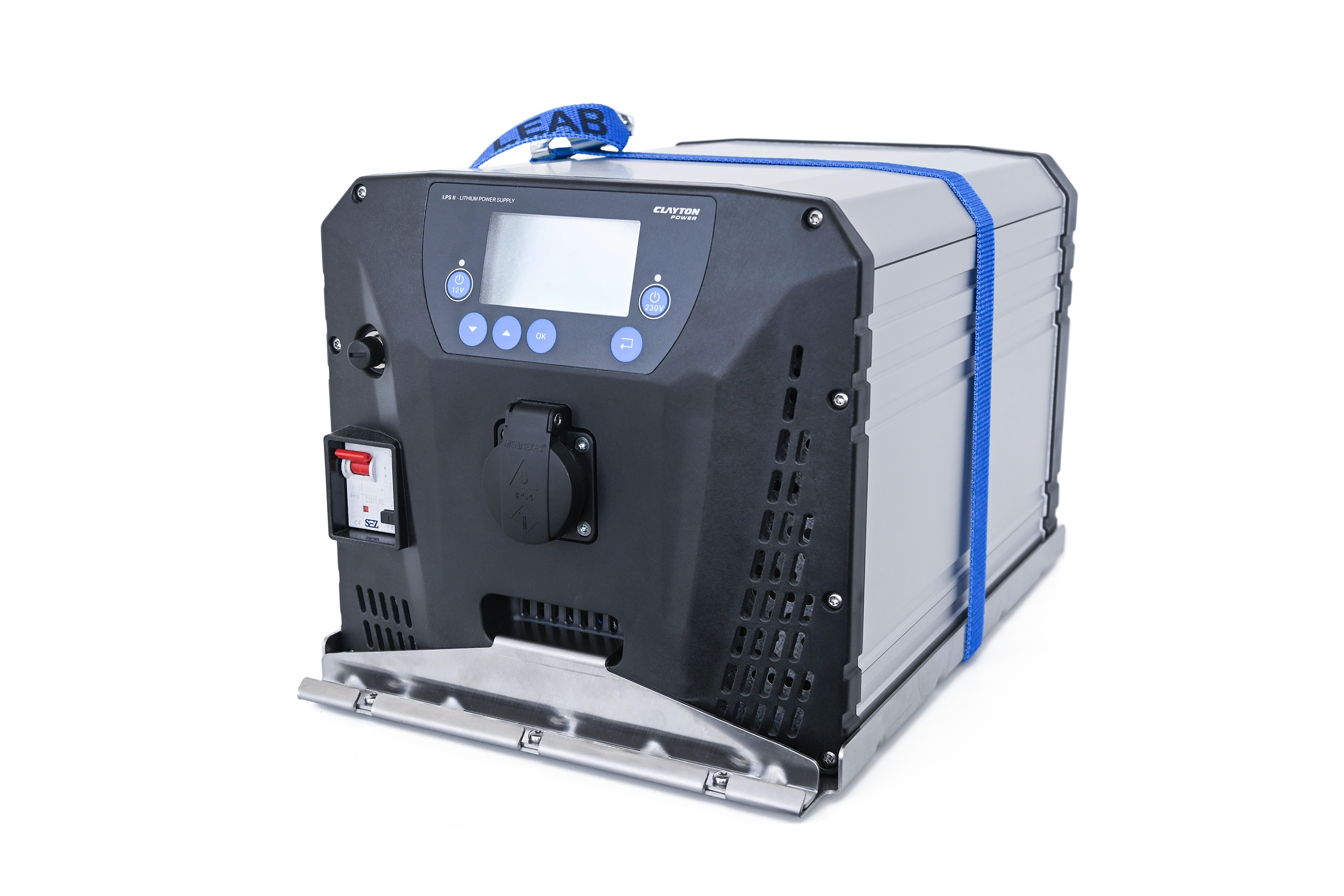
Is the LPSII right for a Leisure setup in a T6 campervan.?
+++


right im going to put myself out there for some hefty criticism.

because i think -

No, the LPSII is not the best option for a T6 camper van.
+++


why? - whats bad about it?


its a big unit
, that you cant fit under a seat vs a nice compact 100ah under-seat lithium + inverter. space is at 100% premium, and squeezing your 12v leisure install into seat bases is a better solution as it gets you more space in the back of the van.

the inverter is not the best for efficiency - my Renogy 1000w gets left on all week in the van and wont run the battery flat. so the LPSII need to be constantly kept an eye on or it will run flat within a day with the 240v on and just a small load like a Compressor fridge. - not great when camping.

the capacity is too small - 80ah usable (from the 100ah internal battery) is just not enough to see you through a camping weekend. - they are talking about extra batterys being available in 2024 - or you can hack in a buffer battery like i did.

its very expensive for what it it. - you can buy the separates and diy for less cash.

No APP for monitoring - but its coming in new LPSII units 2024


+++

What is great about it?


well the DC charge speed from the engine bay is impressive - and the best I've seen yet.

the DC output is very capable compared to other PPP, but on par with a standard lithium battery setup

it has a good solar MPPT built in - separate from the DC in.

the jumpstart feature is brilliant - but he relies on a direct link to the starter battery, and not using a buffer battery setup.

the SUPER CHARGER is nuts - 90/100A charge rate is amazing.


+++


so where do i go from here?


well i love the LPSII,

in fact I've just bought the LPSII REMOTE to go with. . . its on its way now.

I've also emailed Clapton Power to ask about the upcoming BT & App feature, and if the LPSII can be retro fitted. . . or seeing as the REMOTE is CAN bus - can they make a REMOTE with BT, so that all the existing LPSII users can have that feature. (i also asked about the upcoming extra battery's - lets see what they come back with.)

ill be using this as a portable camping setup. with the 230ah ROAMER seat base buffer battery. . . for the foreseeable future. (but i wont be hard wiring it in)


or even a coupe of @Dellmassive 100Ah battery boxes. . .

it will stay a Portable power solution - like the EF Delta2 and others

ill have to add in the normal 400w solar to see if i can get through a 5day camping trip. . .


+++


so what about the BUS, i was going to fit in in there . . . . but now I've decided its just not right for me.

having the SWB T6, there just isn't enough space for this setup.

I've decided i will be better off fitting a 230ah seat base battery under the seat, with standard 12vdc from that.

with a 50A dc-dc charger, like the Orion XS or Renogy IP67 or Renogy DC50s or a REDARC as they are small.

and add in a 1/1.5/2kw inverter under the other seat base. with associated EHU consumer unit, with the EHU point under the bonnet.

ill run separate 240ac sockets for the Inverter feed / EHU feed to save the earthing arrangement mess.

and ill fit the Derv Heater under the van in the OEM location with the OEM ducts.


1707044143755.png


+++++


and what of the LPSII when the BUS is fitted out with its camper setup . . .and we dont need it as a Portable solution ?


we`ll ill be fitting it in the (work) VAN . . as its a daily driver, and running the engine is not a problem.

we dont have or need fitted solar - but can add some portable if needed.

the jumpstart feature will be great.


but i have a better idea. . . .


that as i already has a Fogstar 230ah seatbase battery. . . .

and a 50A dc-dc charger. . . and a 1000w Renogy inverter . . .

ill remove the inverter, and fit the LPSII in the back of the van and connect it to the 230ah seat base battery.

that way the 230ah will act as a buffer battery . . .giving the LPS 330ah of effective battery capacity.

the LPSII 2500w inverter will cover all my mobile power needs.

and the 50A charger will charge both the 230ah seat base and the LPSII at the same time. - we can even add in a IGN Toggle switch to enable/disable the LPSII charging side.


..


1707044971513.png


so thats my ideas and thoughts on the LPSII . . . and why its not right for me to fit in out T6 as a fitted leisure battery solution.
.

.

but the future is bright for the LPSII


and i just hope they offer a REMOTE that enables the BT feature. . . . so we can all have the APP in the near future.


.
 
  • Like
Reactions: CAB
As a thought if you have a number of your power boxes you don't need to have all the power in one place and distribute it at 12v the way you do 240v, you can have small zones around a power box.

That may make more efficient use of the stored charge.

This is the way I run the event PA, each amp point has an 18l Really Useful Box with 40Ah or so of SLA in on Andersons
 
An upside of the Clayton type units is that pretty much everything high current is in one place, which is easier for those not experienced at wiring.

In particular it makes the oft desired usecase of "I just want the 240v sockets to work on and off EHU" straightforward and safe as it deals with all the knarlly change over of earth bonding that most don't even realise needs to be done to be safe.
 
Back
Top