Inverter fuse and cable size?

Eddy7

Member
VIP Member
I've got a Sterling ProPowerQ 350W Inverter which the instructions tell me I should install with a 60A fuse, however the cables are 12AWG which I belive equals 3.31mm

3mm cable 33Amp Single Core Thin Wall Cable - 3.0mm² 33A

How can this be right, the fuse is rated so much higher than the cable?

Many thanks,
 
The Sterling ProPowerQ 350W Inverter has a peak power of 600W and continuous operation of 350W .... input voltage is rated from 10V - 15V
Peak power (600W) divided by their lowest operating voltage (10V) gives a peak current of 60A - peak, not continuous .... but hence the 60A fuse.

I would hope that Sterling have used cables capable of complying with the specification of their device.
 
As above...

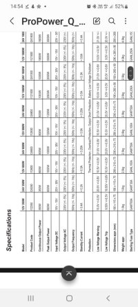
Guide shows 60A fuse.

But doesn't show cable gauge.


.


Screenshot_20220830-145422_Samsung Notes.jpg
 
16mm² seems to be the recommended size for 60A, that's assuming the length of cable isn't excessive.
 
Thanks all.

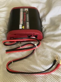
I was refering to the cable size that's attached to the inverter as delivered from sterling as I couldn't understand why the cable is lower rated than the fuse specified.

I got the 60A fuse spec from the document @Dellmassive attached.

There will only be about 20cm of cable from the battery to the fuse then straight into this cable which is attached to the inverter.

@Oceanis explanation sounds reasonable, If peak power is 600W / 12V = 50Amps which is above the cable spec, but should only occur briefly.
But continus output is 350W / 12V = 29Amps which is below the spec of the attached cable.

Just looking for a bit of reasurance this all sounds right.

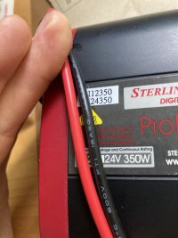
IMG-4267.jpgIMG-4254.jpg
 
Investigating a little further the first thing the live goes to in the inverter is an internal 40Amp blade fuse, so it looks like it can't draw anymore than 40Amps anyway.
 
You can always down rate the fuse.

35A is the max I'd expect to see with a healthy battery with good voltage.

So fusing at 40A should be fine on loads under 350w.
 
Investigating a little further the first thing the live goes to in the inverter is an internal 40Amp blade fuse, so it looks like it can't draw anymore than 40Amps anyway.
Not quite, it depends on the blow time of the fuse. The max rating for the device is 600W which it cannot sustain continuously and which at 10V is 60A .... the 40A fuse will probably never blow at this current, but it will get hot.

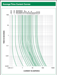
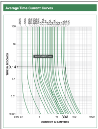
A typical fuse blow time chart looks like this ...

1661874098371.png

The 15A fuse would take more than 100 seconds to blow @30A - it would get very hot - which is why it is necessary to fuse wires correctly, otherwise the fuse holder might melt.

A 40A fuse will survive long enough for the AC load to get going and start drawing less current - the inverter will drop to its continuous output of 350W, which at 10V is ~35A - so the 40A fuse will be fine. The inverter will almost certainly trip and shut-down before the internal fuse blows, but it will allow a peak of 600W for a short time to get equipment with a high startup load going.

An external short circuit of the wiring however will draw as many amps as the battery can provide.

In this situation, the internal 40A fuse is not going to get any current because the wire is shorted before the inverter, here the external 60A fuse will blow pretty quickly because the battery can supply hundreds of amps.

I wouldn't overthink this ... best just follow Sterlings instructions and put a 60A fuse on the supply ... there are thousands of these in service with 12 AWG wiring.
 
Not quite, it depends on the blow time of the fuse. The max rating for the device is 600W which it cannot sustain continuously and which at 10V is 60A .... the 40A fuse will probably never blow at this current, but it will get hot.

A typical fuse blow time chart looks like this ...

View attachment 170706

The 15A fuse would take more than 100 seconds to blow @30A - it would get very hot - which is why it is necessary to fuse wires correctly, otherwise the fuse holder might melt.

A 40A fuse will survive long enough for the AC load to get going and start drawing less current - the inverter will drop to its continuous output of 350W, which at 10V is ~35A - so the 40A fuse will be fine. The inverter will almost certainly trip and shut-down before the internal fuse blows, but it will allow a peak of 600W for a short time to get equipment with a high startup load going.

An external short circuit of the wiring however will draw as many amps as the battery can provide.

In this situation, the internal 40A fuse is not going to get any current because the wire is shorted before the inverter, here the external 60A fuse will blow pretty quickly because the battery can supply hundreds of amps.

I wouldn't overthink this ... best just follow Sterlings instructions and put a 60A fuse on the supply ... there are thousands of these in service with 12 AWG wiring.
From that chart can I ask where you get the fact “15A fuse would take more than 100 seconds to blow @30A”?
 
From that chart can I ask where you get the fact “15A fuse would take more than 100 seconds to blow @30A”?
Sorry, my mistake, really must use a bigger screen ... @Gavinda is right, 1-2 secs, maybe quicker ... my bad.

The point I am trying badly to make is that a fuse can spend a considerable amount of time carrying more than it's constant rated load before it blows, in the case of the 15A fuse in the diagram above it could withstand 24A indefinitely, maybe more if it was in a fuse-holder that was a good heat-sink. That's more than 60% over its constant current rating.

A 40A fuse may well withstand 60A for a very long time - certainly long enough for the inverter to decide if the AC load is too big to handle.
 
It's a logarithmic scale on both axes ... which is good if you want to display percentage change or multiplicative factors, but a pain to read.

The point @Skyliner33 marked is indeed 0,5 secs ... each line is a 10th of a sec ... 0.1 0.2 0.3 etc. .. they are spaced the way they are because it is a logarithmic scale.

 
Last edited:
Pedantry aside, I'd think that if the inverter came with those cables it'll be ok to use them as long as you don't make them any longer, I would however use a fuse of a lower rating.
 
Pedantry aside, I'd think that if the inverter came with those cables it'll be ok to use them as long as you don't make them any longer, I would however use a fuse of a lower rating.
Hmm ...

I wouldn't ... a fuse of a lower rating would run hotter when the inverter is at it's temporary "peak" load - I've seen melted fuse holders where an underrated fuse has been used - high enough rating to sustain more current than its rating, but low enough to get very hot while doing so without blowing.

The 60A fuse is to save the wiring from a short, which would be loads more than 60A - that's probably why the recommended external fuse is 60A - and the external fuse is not to protect the inverter, it has its own 40A fuse for that.
You're probably right, I'm just used to a fuse being sized to protect the wiring.
 
You're probably right, I'm just used to a fuse being sized to protect the wiring.

I think 12 AWG is a bit small, but only Sterling know the true characteristics of their device and they chose 12 AWG and specified a 60A fuse. :confused:
 
Yep my bad. 0.5s.

Also it depends if that chart is for slow or fast blow fuses. (Pedant mode again sorry).
 
Back
Top