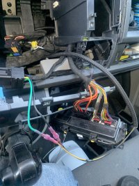
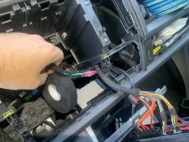
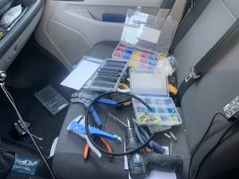
The wire is now connected to pin 1 on the webasto, and embeded with the original wire loom. A stealthy install.. Nope! Not even close.. lol
A 8mm spanner / wrench, for the removal of plastic cover underneath the car
A 13mm spanner / wrench to the adblue tank
pliers to remove those pesky rusty push on nuts on the plastic cover.
I must say, been on the back for an hour or 3 in gravel, doin this job was not fun at all.
So if i have wraped my head round this correctly, If i connect this wire that i have just pulled to one side of a relay and the other side to ground, the faultcode for heater blower should not be present anymore?

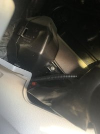
So now I need to sniff out where this T17a connector is hiding behind the glove box. Do you have a picture of that connector location?
If that pin 1 on T17a gets 12v from somewhere else, the fan should run at any set speed on the dail if my thoughts are correct. I want to give this a try..
Not sure if there is a main blowerfan relay or how that is connected, if its a relay then its for sure monitored and injecting a voltage on it might upset the vehicle with faultcodes and other "fun" issues
 
So if i have wraped my head round this correctly, If i connect this wire that i have just pulled to one side of a relay and the other side to ground, the faultcode for heater blower should not be present anymore?
That's my thought, too.

T17a connector is hiding behind the glove box. Do you have a picture of that connector location?
Unfortunately the wiring diagram is not that detailed.

Having had another look into this - it indeed feeds the power to the blower. However, it doesn't seem to be permanent +12V. So it won't help you because you need permanent +12V to run heater blower without ignition on.

Not sure if there is a main blowerfan relay or how that is connected
It's something internal to AC controller.
 
So It has not permanent 12v, thats fine, same was the other work van i had. Just pick up permanent 12v from somewhere, and that should not be any issues.
My thought is to connect power to the AC controller when the webasto is running.. Seems like I have to dismantle the AC to have a poke around to see what wire feeds it and feed it 12v to see if the controller operates normaly.. this will be intresting
 
Perhaps im lucky enough to be able to inject 12vs on one of these wires to make the controller work.. mmmm intresting

image.jpg
 
Perhaps im lucky enough to be able to inject 12vs on one of these wires to make the controller work.. mmmm intresting
I believe it's connector T5r as per my previous post #476.
The thick red/yellow on the left is the normal feed for the AC controller.

Webasto controlled feed taps into orange/yellow (2nd from right/pin 2) - speed 2 - St.2.
 
I can not find a red/yellow wire behind the glovebox. But applying 12v to a red/yellow wire on the back of the heater control i get full controll over the blower fan speed.
So in this case I want to tap in to pin Red/yellow wire so I can select the fan speed I want.. now where does that wire end up? in the Engine compartment?
The AC controller has permanent 12v and are "woken up" by can signal.. So in my messed up brain, something tells me when the telestarts triggers the webasto to run, the webasto transmit a wake up signal to the AC controller then turns the Steppermotors and blend motors for temp control. There might be more wizardery goin on that I do not know of.
 
Last edited:
So in this case I want to tap in to pin Red/yellow wire so I can select the fan speed I want.. now where does that wire end up? in the Engine compartment?
Now that's something different :thumbsup:
The red/yellow ends up at fuse SC2 via X-relief relay etc.

he AC controller has permanent 12v and are "woken up" by can signal..
I believe the Climatic AC controller does not wake up with CAN command thus you still need to use a relay driven by Webasto to power up AC controller - either just the Speed 2 or (possibly) full AC controller...
 
WEl.. I do like to think ouside the Box if you see what i mean... where is this SC2 fuse located and wtf is this x-relief relay? Where does it live?
 
where is this SC2 fuse located and wtf is this x-relief relay? Where does it live?
SC2 is located in fuse carrier in passengers footwell (left column 2nd from bottom, 60A).

During engine cranking X-contact relief relay switches off a number of big electric consumers, e.g. heater blower, etc.
On LHD van the relay is located by the SC fuse carrier top left - has a "644" designation on it.

WEl.. I do like to think ouside the Box if you see what i mean...
Sure, I do like new ways to implement things - actually I have planned to replace the blowers resistor pack for "speed 2" with a PWM power supply to reduce the current the blower draws. The current draw 6 Amps is just crazy waste of battery's limited energy when running Webasto without engine running - a lot of energy just wasted in the resistor. With PWM the current would be reduced down to approx. 2.5 Amps - thus enabling to run Webasto a lot longer without flattening battery.
 
Im still clueless on what pins on the telestart module I have to use to get this working.. I have a loom and a connector, but the colors doesnt match up with any pictures posted here at all. Need a bit more aid lads if I may before i burn the damn car up ;->
 
Its sorted.. The wiring is correct.. Connected up the telestart, fired up Vcds and clikced on 18, What do you say what do you know, the telestart showed up as a slave module.
Result!

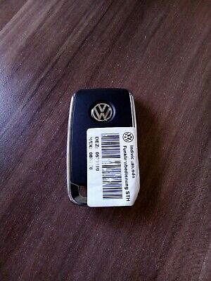
no remote was provided with it and the one i have does not work, so now the hunt begins for a remote.....
 
You need to get your remote paired with your Telestart.
See below, just read the manual.
 
  • Like
Reactions: mmi
Yes, the controller 3Q0 963 513 A works with the remotes 3G0 963 511 (oldest), or 3G0 963 511 A, or 3G0 963 511 B (latest).

Remote sync how-to:
 
(7N0 963 513 B) with the car.. its not labeled as LIN on it only Wv sticker on it and on the oval remote.
True, that oval remote definitely can't sync with 3Q0 963 513 A-controller.

Details of the remotes incompatibility here:
 
Back
Top