[Resolved] dc-dc and starter battery fuse blown

ArtD

Member
T6 Pro
Hi there, I'm looking for some advise what is going on with my connections i.e.:

I have finished installation yesterday with renogy dc-dc/mppt 50A to my fogstar 230Ah. See below diagramDiagram.PNG
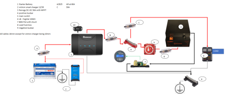
And everything worked i.e. including load however, I decided to leave victron charger on to recharge LB and 4 min later the fuse A (60A) blown
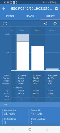
It got interrupted within 4min reading 14.59V at victron history.

So I though I wil replace with another one and this what I have noticed:
First I put LB off charging/discharging and main switch off too.

1. dc-dc charger was showing alternator is on (red light) and battery on (normal mode) however no enging was running and no victron connected to the mains for charging
2. when connecting victron - no change to the light on dc-dc
3. when switched engine on - the light on the dc-dc alternator (red on) dissapeared
This was very confusing why?

In all above I have main switch off and LB was off for charging/discharging

then I turned LB on charging/discharging and all was still ok

then I switch main switch on and the fuse blown again.

I'm looking for some advice on the following i.e.

A. Why dc-dc behave like the alternator is charging even when enging is off (this is not smart alternator) - I thought that Starter Battery voltage might be high but not - it was 12.77V
B. why dc-dc doesn't show charging when enginge on - the red light dissapeared?
C. main switch - working pattern - that blows the fuse?
D. should LB be on all the time?

thanks a lot for info
 
Which fuse blew? If I’m reading your diagram right, there are three 60A fuses in your system.
 
Why does the Victron charger go to the SB and not the bus bar for the LB?
You look to have the alternator current and the Victron current going through the fuse at the same time as soon as you turn the isolator for the battery.
I’m guessing the current doesn’t flow through the dc-dc until you turn the battery on and boom.
I only have a very basic understanding though.
@CJW fuse A blown - one between battery and dc-dc
@Bigsidavies - victron charger was not on when fuse blown - but alternator was on. I connected it to starter as easier with cabling to unplug when needed and been advised by Dellmassive that it is ok due to the fact that as soon as starter battery would be full victron charger would increase voltage and trickle dc-dc to start charging and actually it worked exactly like this.
 
Got a few pics of the install and setup.

Pic says a 1000 words and all that.
 
Why have you got 2 DC chargers coming from the starter? I suspect this is the issue here. If both chargers are trying to feed into the leisure then that's gonna be 80A!!
 
@ Howzat - there are no 2DC chargers at the same time i.e. either alternator when starter is on or victron charger plug in. there are no two at the same time
 
So fuse A blown. 50A.

Post a pic Of that conection.

What's the dc50s set to?.. lithium? 50A?.... Have you tried setting the current limiter to lower, say 30A?

Post a pic.of the DC50S connections as well.
 
@Dellmassive - photos included with some explanation, it is small area under seat so to show it all I would have to disconnect which I didn't want to initially. In case it isn't readable on the photos:

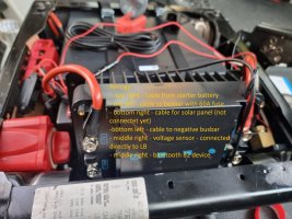
Photo 1 - renogy dc-dc: top right - lead from starter battery, bottom right - solar panel connection (no connection yet), middle right - voltage sensor - connected directly to LB (positive to positive and negative to negative), top left - lead to positive busbar with 60A fuse in between, bottom left - lead to negative busbar

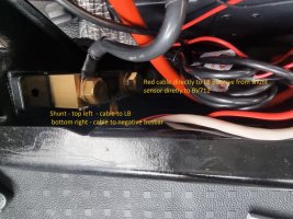
Photo 2 - Shunt - top left - connection to LB directly, bottom right connection to negative busbar

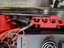
Photo 3 - this is very small area to show and couldn't pull out unless disconnecting all but the order is as follows:

Positive busbar:
- from LB cable to main switch (ignore that it is black I was short of red cable at the end) with 60A fuse in between,
- from main switch cable to positive busbar (no fuse there)
- from renogy as per Photo 1 connection to positive busbar (60A fuse)
- to load cable with 50A fuse

Negative busbar:
- from shunt to busbar
- from renogy to busbar
- from load to busbar
- from busbar to ground (under seat one - I have checked it with multimeter and it was working well)

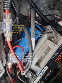
Photo 4 starter battery
fuse at the top left 60A - main one between dc-dc and starter battery - this one blows out
fuse at bottom left - fuse for victron (40A) (I haven't connected victron through anderson plug yet)

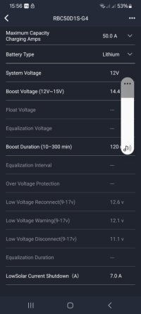
Renogy setup lithium at 50A Photo 6
last reading for victron attached as Photo 5 (I haven't set anything from victron left as normal)

20240309_152604.jpg

20240309_152615.jpg

20240309_152623.jpg

20240309_152516.jpg

Screenshot_20240309_102511.jpg

Screenshot_20240309_155629_DC Home.jpg
 
Last edited:
Have you got the IGN+ or Engine Running signal going into the Renogy dc-dc?

I can’t see how you’d get more than 30A at fuse A without the Renogy thinking the engine was running.
 
If your LB is low, and the dcdc thinks the engine is running, it will draw up to 50A from the SB.

Assuming you haven’t got a problem elsewhere, could the SB charger being switched on have tipped it over 60A?
 
If your LB is low, and the dcdc thinks the engine is running, it will draw up to 50A from the SB.

Assuming you haven’t got a problem elsewhere, could the SB charger being switched on have tipped it over 60A?
There is no smart alternator so renogy indicates no need for IGN+ signal, just voltage signal to LB;
LB was at 30% when started charging, 2 cycles ok - I tried one with aternator and another one with victron - charged to 60%, then decided to charge again with victron to 100% and I got to 4min charge only and fuse blown
 
Is there a T6 that doesn’t have a smart alternator? All have stop/start I believe?
 
OK. Is your Victron outputting at a voltage that fits this description for a trad alt?
IMG_6208.jpeg
 
Where I’m going with this is maybe the Victron is supplying a voltage that fools the Renogy into thinking the engine is running.
 
Where I’m going with this is maybe the Victron is supplying a voltage that fools the Renogy into thinking the engine is running.
I was wondering about that. I'd be tempted to wire the victron directly to the LB or at least pull it out the loop to test the DC side.
 
Back
Top