I'm aware that this post is a bit wordy, so I have highlighted my queries in bold to save those that are easily bored! 
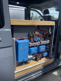
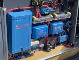
Back in 2020 I ordered my new T6.1 and I impatiently purchased all sorts of components and planned what I considered to be the ultimate set-up for my off-grid machine.
Whilst the "Order Delays" thread grew and grew, I ended up with shed loads of kit including a 200Ah (Gen1) Roamer Battery, which sat for 15 months before it eventually got installed in my new van in March 2022.
The battery had sat for 15 months and like an idiot I didn't charge it at any time during this period. I consequently found that the cell overvoltage warning was triggering once I got around to installing this in the vehicle. Here is a screenshot from the summer showing the overvoltage issue :

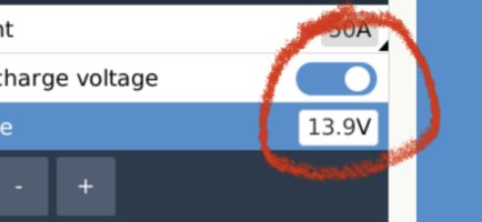
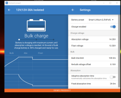
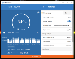
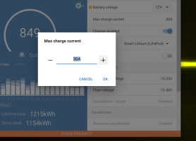
I spoke to the helpful guys at Roamer and they got me to tweak seem BMS settings and told me to reduce the absorption voltage to 13.9V and then "creep it back to 14.2 volts over the coming months, once the BMS stopped triggering overvoltage warnings. They were helpful as they could be and advised me that a cell delta of up to 0.3V is fine.
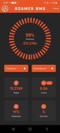
Whilst mucking about with this battery, I noted that the capacity of the battery was set at 180Ah on the BMS. (This was as it was configured when it was delivered, so I assumed that this would be correct.) I always had my Victron Smart shunt set as 200Ah capacity and the "% charge" info from the Victron was always more reliable than the figure viewed on the BMS. I therefore changed the setting within the BMS to the 200Ah figure.
Since changing the BMS's Battery Capacity to 200Ah I have had consistently reliable results from both the BMS and the Smartshunt in terms of "% charge", but, I set the "Total Cycle Capacity" to be the same as the "Total Battery Capacity" - Not sure of this is right, so if anyone can confirm that would be useful?
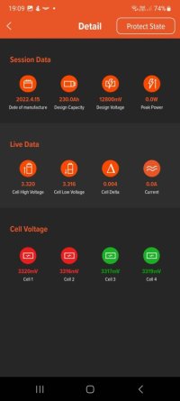
So....... back to the cell balancing topic; It has taken me ages to get to a point where I have got the battery to reach the end of its absorption without triggering the overvoltage warning. This can be seen below:
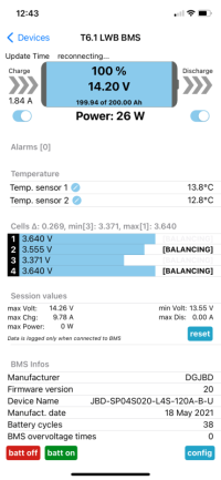
Roamer have confirmed that my Delta figure of 0.269V is within spec, as it is less that 0.3V (Shown in the above picture as 0.269). I consequently don't want to bother them with my queries, as the battery is operating within the parameters that they have defined.
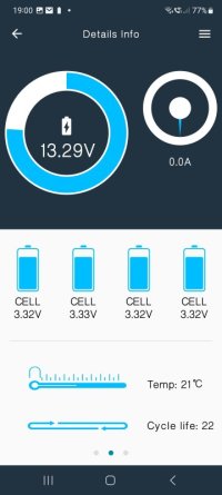
This is an expensive battery and I'd like it to last as long as possible. The battery has currently cycled 38 times and I was hoping that the maximum Delta figure would come down to the 0.15V as per the "Delta to balance" shown below.
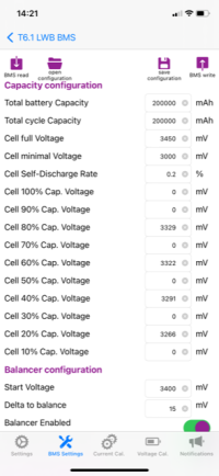
It seems that the cells will never, ever truly get balanced and that cell 3 will be weaker than cells 1, 2 & 4.
Back in 2020 I ordered my new T6.1 and I impatiently purchased all sorts of components and planned what I considered to be the ultimate set-up for my off-grid machine.
Whilst the "Order Delays" thread grew and grew, I ended up with shed loads of kit including a 200Ah (Gen1) Roamer Battery, which sat for 15 months before it eventually got installed in my new van in March 2022.
The battery had sat for 15 months and like an idiot I didn't charge it at any time during this period. I consequently found that the cell overvoltage warning was triggering once I got around to installing this in the vehicle. Here is a screenshot from the summer showing the overvoltage issue :
I spoke to the helpful guys at Roamer and they got me to tweak seem BMS settings and told me to reduce the absorption voltage to 13.9V and then "creep it back to 14.2 volts over the coming months, once the BMS stopped triggering overvoltage warnings. They were helpful as they could be and advised me that a cell delta of up to 0.3V is fine.
Whilst mucking about with this battery, I noted that the capacity of the battery was set at 180Ah on the BMS. (This was as it was configured when it was delivered, so I assumed that this would be correct.) I always had my Victron Smart shunt set as 200Ah capacity and the "% charge" info from the Victron was always more reliable than the figure viewed on the BMS. I therefore changed the setting within the BMS to the 200Ah figure.
Since changing the BMS's Battery Capacity to 200Ah I have had consistently reliable results from both the BMS and the Smartshunt in terms of "% charge", but, I set the "Total Cycle Capacity" to be the same as the "Total Battery Capacity" - Not sure of this is right, so if anyone can confirm that would be useful?
So....... back to the cell balancing topic; It has taken me ages to get to a point where I have got the battery to reach the end of its absorption without triggering the overvoltage warning. This can be seen below:

Roamer have confirmed that my Delta figure of 0.269V is within spec, as it is less that 0.3V (Shown in the above picture as 0.269). I consequently don't want to bother them with my queries, as the battery is operating within the parameters that they have defined.
This is an expensive battery and I'd like it to last as long as possible. The battery has currently cycled 38 times and I was hoping that the maximum Delta figure would come down to the 0.15V as per the "Delta to balance" shown below.

It seems that the cells will never, ever truly get balanced and that cell 3 will be weaker than cells 1, 2 & 4.
- Is that normal to have weak cells?
- Are the cells likely to get balanced eventually?
- How long would you expect them to fall in line with the other 3 cells? (as in number of charge cycles.....It has currently been 38!)
- Should I creep the absorption voltage a little higher than 14.2V (Say 14.4V, over the next ten charges or so) and then reduce this figure back to 14.2V in the future, in an attempt to get the cells more closely balanced at 14.2 Volts?
- Should I try something else to reduce teh Delta figure?

