[Guide] DC-DC Charger (for leisure battery) -- How I Done It --

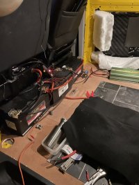
I think he's swapped out the cheap £60 LION battery for a £180 YUASA battery. (Starter battery?)

so off came the 60 quid from euro car parts lion battery, on went the 180 yuasa replacement.

At that price it must be a decent AGM.... I'd assume anyway.
 
I think he's swapped out the cheap £60 LION battery for a £180 YUASA battery. (Starter battery?)


At that price it must be a decent AGM.... I'd assume anyway.
apologies for confusing.

this is the starter battery that replaced the non stop start one.

as far as i can tell, it ticks the big enough box and the AGM box.

leisure battery is 110aH so big enough to handle the current a DC-DC will throw at it.

im going to move onto sourcing the right DC-DC but going to use this as an opportunity to sort the electrics out and maybe add a few more usb for the kids devices. appreciate the input so far, thanks.
 
Hi,

I fly drones for work so we have high power usage.
Just getting round to transplanting my monster leisure setup from my old pathfinder truck.
It has 3x 120ah AGM batteries & a 2000w inverter.

dc-dc charger is the ctek 250se coupled with the ctek 120 smart pass for fast charging.

Question is what should I do about the factory leisure battery?
I have no idea how old it is so don't want it in the same circuit as my 3x other batteries.

Should I leave it charging via the crappy split relay & just run my extra thick wires to the main battery for the 3x leisure batteries?

 
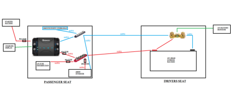
diagram.png
Can someone let me know if this setup looks ok?

I allready had the factory aux battery so I'm using the existing wiring for the dc charger but swapping the relay out and adding a 80a midi fuse
 
Does the Renogy charge the starter battery at any point? If it does, I'd put another fuse close to the Renogy to protect against shorts towards the starter battery. (mind you, that's was assuming the fuse shown was close to the starter. If the factory wiring isn't connected when the ignition is turned off then there's no point)
I have a similar setup, but with the battery and shunt under the passenger seat and the inverter on its own under the driver's seat instead of the passenger seat.
I have a fuse between the battery and the busbar, but none in the feed to the inverter, figure the battery fuse would suffice for such a short run that is under the floor.
 
Last edited:
the 80a fuse is close to the renogy. I dont think the renogy charges the starter battery?
I suppose adding another fuse between battery and busbar wouldnt hurt..
 
View attachment 144853
Can someone let me know if this setup looks ok?

I allready had the factory aux battery so I'm using the existing wiring for the dc charger but swapping the relay out and adding a 80a midi fuse
looks good . . . . but.

id remove the ground link and just use chassis ground in both seat bases.
id add a second main fuse next to the battery, or move the inverter fuse over.
id fit a master battery on/off switch next to the battery.
id fuse ANY connection to the battery, included the shunt supply
id make sure the original feed from the starter is fused. (should have 100A if oem)
id set the main powers and ground to the same AWG, so if using 1awg for the POS, then use 1AWG for NEG, not 6 or 4 AWG (keep main powers same size)


1644092515235.png
 
thanks for the advice and sketch!

i've updated my little diagram. Am I ok leaving the wires from the renogy at 6awg or are you saying I need to change them to 1awg aswell?
diagram.png
 
thanks for the advice and sketch!

i've updated my little diagram. Am I ok leaving the wires from the renogy at 6awg or are you saying I need to change them to 1awg aswell?
View attachment 144860
The Renogy guide calls for 6 or 4 awg depending on distance...

So that's ok.

The main thing is you big power item.... The inverter. So as long as the inverter power feeds are large enough..... Your diag shows 1awg from battery to inverter to busbar to ground all same thickness.....so should be ok.
Thanks! I can get started on this tomorrow now :)
 
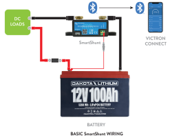
Personally I would follow the manufactures advice for fitting the smart shunt (£120). Otherwise how can you guarantee the readings are correct. They always have all the loads on bus bar then to one earth point. Both plans posted above may work.


If you don’t want the shunt then send it back and grab a bog standard battery volt meter which attaches to the battery positive & negative. £25

Hope that helps.

05-Installing-A-Battery-Monitor.jpg

C147EB7B-F5DD-4AD5-907D-96F55E037E48.png
 
Last edited:
Your first plan was right as Your smart shunt (£120) won’t work / show accurate results the way you have it wired with dual / triple earth points. You need the ground of everything you want to monitor (usually everything) to be run via the shunt. They work by measuring the resistance or similar on the ground side. Then they can show you what ah you have left.


If you don’t want that then send it back and grab a bog standard battery volt meter which attaches to the battery positive & negative. £25

Hope that helps.

View attachment 144898
That's incorrect information.

The body ground is preferred ground return as it's lower resistance.

The shunt will meter all current in and out of the battery with a body ground.

The victron diagram is figurative.
 
Personally I would follow the manufactures advice for fitting the smart shunt (£120). Otherwise how can you guarantee the readings are correct. They always have all the loads on bus bar then to one earth point. Both plans posted above may work.


If you don’t want the shunt then send it back and grab a bog standard battery volt meter which attaches to the battery positive & negative. £25

Hope that helps.

View attachment 144929

View attachment 144898
Voltmeters can't be used on lithium Batterys as an indication of state of charge as the voltage stays constant for 90% of the capacity.

The diagram you show above relates to a marine installation that uses a wooden or fibreglass hull.....in a boat that has no ground chassis they use the shunt or ground busbar.

In a van istall you use the chassis as ground.

The T6 already has a shunt on the Starter battery from factory..... And it meters all power in the van from numerous ground points around the van.
 
- NEW VERSION -

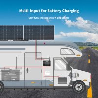
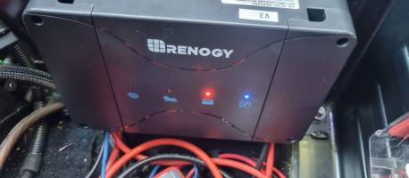
Renogy combined unit (all in one) 50A DC-DC & Solar MPPT & Starter trickle charge from solar

they do a 30A version too.


DCC50S 12V 50A DC-DC ON-BOARD BATTERY CHARGER WITH MPPT(NEW VERSION)​


1644675986982.png


05__36734.1635328614.jpg-06__76668.1635328619.jpg07__44482.1635328609.jpg-04__23251.1635328621.jpg-02__26354.1635328593.jpg-03__62611.1635328595.jpgF-B11A45201AB2__71642.1602834149__60855.1642647836.png


DCC50S 12V 50A DC-DC ON-BOARD BATTERY CHARGER WITH MPPT(NEW VERSION)​

 
Is it not better to have separate dcdc and mppt in case one fails …??
maybe,

some people may have that opinion.

but if your limited for space then a combined unit can be an option.

separates . . . combined . . . . either way - i own and run both setups.

not had a combined unit fail yet.

but for a Combined unit with the monitoring & APP the Renogy DC50S will take some beating.

its my current prefered DC-DC that im running now. ( due to the fact that i can set the current limit so i done cook my install as it needs beefing up to be able to handle the full 50A it will deliver and the Lithium battery will take)


+++++++++++++++++++++


current setup is:


Renogy DC50s DC-DC + MPPT ( no solar connected ) + BT-2
Renogy 100ah Lipo4 + BT-2
Renogy 1000w inverter.
Victron BMV712 monitor

1644684949015.png
1644684783330.png1644684810514.png1644684821482.png


+++++++++++


FWIW . . .


Even though i run these combined units. . . .

i still just run Victron MPPT side by side. . . . . options.


1644685084448.png
 
Hi any tips / advice for my circuit?

- 4x agm batteries
- 1500w inverter
- Victron bluetooth energy shunt
- ctek 250se
- ctek 120 smartpass

All the cables are 70mm (475amps) except the below.

At the moment Im using the factory leisure battery feed cable (110amp cable) into the ctek (20amps)
I cut off the input to the factory split replay and fed into the ctek via a 30amp fuse.
This cable is fused with 30amp fuses at starter battery & ctek end.

In the future I will feed my 70mm cable in from the engine bay to the passenger seat & that will be fused at 300amps both end.
When I do that I will add in the ctek 120 smartpass so total up to 140amps from both cteks.

- One question do I now need to remove the coding for the factory leisure battery system?

Cheers


tempImage1chlnh.jpg

tempImageaaUNka.jpg
 
Last edited:
Back
Top