Towing electrics ex RAC

Ok, thanks; I've just paid for the VIP membership.

:thumbsup:

"Most folks replace the relay completely" - I'm guessing you meant bypass the relay?

Yes, bypass or even remove it completely. Many remove or relocate the fuse/relay brackets and tuck the connectors under carpet. Space is premium especially under single seat and it will be tight to fit a battery and all leisure electrics into the seat base. So, every little bit of removed unnecessary stuff helps.

I would have thought a quality DC-DC charger would know if the engine was running or not anyway, but I'll have to look into this.

Yes and no. Chargers can indeed sense the main battery voltage and turn themselves on based on that. The trouble is that T6 has a smart alternator and battery management system for the main battery - depending on battery SOC the alternator can be completely off even when engine is running. It’s perfectly normal to see anything between 11.9 and 14.9V on main battery with engine running - it makes it hard for dc-dc chargers to be very smart about their charging decisions.
 
If you fit a dc-dc charger the relay is not useful anymore. Most folks replace the relay completely, although you can as well take the relay output to the dc-dc charger and splice into the relay coil feed to get engine run signal. The engine run signal is similar to D+ of the olden days but it goes off with the stop/start - so using that to control leisure battery charging is little bit more intelligent on when exactly to keep the charging on.
I’d be interested in how to do that, I have both 100 and 643 still in place and want to add a Viktron dc dc for my bigger AGM battery.
 
I have an ex RAC van, if you have search you will find me asking about the wiring somewhere. Basically I removed the relay etc and ran a new wire from the starter battery to the rear of the van as that was where I located the leisure battery. I then extended the run signal wire to my dc-dc charger.
 
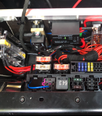
I removed the relay but kept the brackets. In below image blue wire is the engine run signal, I just used a spade connector to pick it up from the relay base.

The main battery wire and the wire to aux battery I butchered away from relay base - now it’s connected like
  • Main battery positive ->
  • 100A fuse in e-box ->
  • 10mm wire from e-box to under seat ->
  • 80A fuse ->
  • busbar ->
  • 30A feed fuse for dc-dc ->
  • dc-dc charger input
So, I kept pretty much of OEM and retained the possibility of adding loads fed from main battery from under seat. Not saying that’s the best way to do it, just how I did it.

1706027963760.png
 
Thanks for that, nice set up. I’ll need to look to see if there is a battery main in the oem loom. I removed the RAC main positive cable.
 
Thanks for that, nice set up. I’ll need to look to see if there is a battery main in the oem loom. I removed the RAC main positive cable.
1706029696056.png

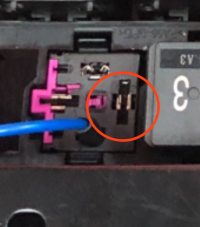
Pop the relay and measure the circled pin. That should be the feed from main battery, same voltage.
 
  • Main battery positive ->
  • 100A fuse in e-box ->
  • 10mm wire from e-box to under seat ->
I think I'll be doing this but from e-box to back of the van (extend wire from relay-in. ) Skip the 80amp fuse and busbar then continue as you have - 30amp to charger.
Then negative busbar and fused positive after.
 
If you are extending to the back of the van you need to consider voltage drop over that length of run, especially if you are considering high current chargers.

If the van was built with standard underseat aux battery the wire run is probably 10mm2 which is good for about 40A without significant drop over the 3m run but will drop further if extended.

The California with the rear battery is built with a 16mm2 cable from the main battery to seat base and then on to the rear with about a 5m run, good for about 35A without significant drop.

Unless you are relatively low current DC-DC like the 20A CTEK you may well need to replace the wiring run from the e-box with something heavier guage.
 
Wut @roadtripper said - was just about to say pretty much the same.

I would add since you don't have 80A maxi blade fuse where I have it, you probably don't have factory second battery. This means the wire used from e-box to the relay can be also 6mm^2 and the fuse in e-box would also be less than 100A in this case.

I'm not sure though if there's configurations with split charge relay but no second battery :unsure:. Can't really see the maxi fuse ampage in your pic, is it 80A or something less? If it's 80A it's probably just in different slot compared to mine.
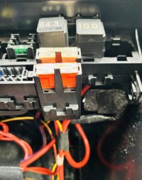
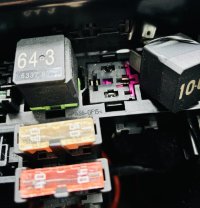
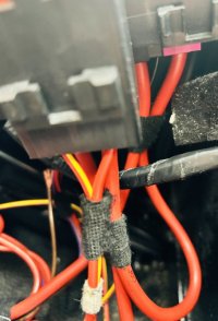
Anyway, the point was that do check the wire gauge and fuses along the line before deciding on whether to keep the OEM feed or not.
 
View attachment 226710

Pop the relay and measure the circled pin. That should be the feed from main battery, same voltage.
Ah I see now. Relay 100 is fed through the loom and out to an 80A fuse then on to battery. Is the ignition live fed from somewhere else? I don’t see another cable?

IMG_7088.jpeg

IMG_7089.jpeg

IMG_7090.jpeg
 
Wut @roadtripper said - was just about to say pretty much the same.

I would add since you don't have 80A maxi blade fuse where I have it, you probably don't have factory second battery. This means the wire used from e-box to the relay can be also 6mm^2 and the fuse in e-box would also be less than 100A in this case.
Without pulling out the starter battery to check, the RAC wiring diagram says there's a 100amp fuse there.
 
Wut @roadtripper said - was just about to say pretty much the same.

I would add since you don't have 80A maxi blade fuse where I have it, you probably don't have factory second battery. This means the wire used from e-box to the relay can be also 6mm^2 and the fuse in e-box would also be less than 100A in this case.
I pulled the 80amp fuse for a little safety while I'm messing around in there
 
Without pulling out the starter battery to check, the RAC wiring diagram says there's a 100amp fuse there.

Ok seeing those photos it's all good - indeed 100A amp fuse in e-box and 80A maxi next to the relay. So the e-box - relay wire will be 10mm^2.

Is the ignition live fed from somewhere else? I don’t see another cable?

If you mean the engine run signal that drives the split charge relay it's just a thin wire from BCM to the relay socket terminal that I had the blue wire in the photo earlier.
 
Using an online calculator and using 10mm2 cable, the drop will be half a volt over 5 meters. @14v nominal input.
Seems OK to me, esp because I'll have solar too.
(thanks for the 10mm info)
 
Using an online calculator and using 10mm2 cable, the drop will be half a volt over 5 meters. @14v nominal input.
Seems OK to me, esp because I'll have solar too.
(thanks for the 10mm info)
At what current?

Also I'd use a lower voltage for planning, you have to account for the DC-DC charger running at a point where the smart alternator is not running (say after regenerative braking) so the whole load of the charger (and van) is being supported by the battery alone. I normally use 12v as a worst case.

You generally want around 3% voltage drop but you want the absolute minimum you can for charging.

Keep in mind DC-DC chargers input current will be larger than output charging current - if they need to boost the voltage to charge that power has to come from somewhere as has the heat lost through the conversion. 1.5 times is a good rule of thumb for planning so assume a 30A charger needs a 45A feed.

Chargers will put a sustained high current load on any cabling, it's really not a good idea to run those at a limit you want as much headroom as you can get.
 
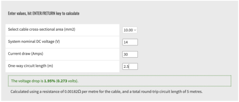
With 12vplanet calculator it's actually less, used 30A here as you mentioned fusing dc-dc with 30A so that's the maximum. Note that you really don't need to account for ground return so I used only 2.5m length since calculator doubles the distance automatically. The van body is a gigantic busbar, basically corresponding to a wire of hundreds of mm^2.

1706099185808.png
 
I must admit @n10n I tend not to omit the return circuit when planning, certainly at high currents, as I think it gives useful overhead and while I take your point the chassis also has resistances at each of the ground points, you don't know what other currents are flowing through those ground points and imperfect conductivity at some points.
 
I must admit @n10n I tend not to omit the return circuit when planning, certainly at high currents, as I think it gives useful overhead and while I take your point the chassis also has resistances at each of the ground points, you don't know what other currents are flowing through those ground points and imperfect conductivity at some points.

Headroom doesn't hurt, absolutely agree on that point. And yes, of course ground connections have to be good and solid. But also, wire ampage limits are really to protect the insulations, the copper itself can take more than what the tables give out. And I think it would take pretty extreme currents to warm the body joints enough to cause issues.

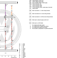
Just to make a point, looking at VW diagrams they merrily run 2.5mm^2 wire from towbar voltage control relay through 30A fuse in seat base and all the way up to the trailer socket, and expect that to be further extended with whatever wiring trailer has. In the below image point 3 goes to the 30A fuse. Ok, they may not expect to support full 30A load on the trailer socket but surely fuse should still be the first one to break?


1706101172817.png
 
Headroom doesn't hurt, absolutely agree on that point. And yes, of course ground connections have to be good and solid. But also, wire ampage limits are really to protect the insulations, the copper itself can take more than what the tables give out. And I think it would take pretty extreme currents to warm the body joints enough to cause issues.

Just to make a point, looking at VW diagrams they merrily run 2.5mm^2 wire from towbar voltage control relay through 30A fuse in seat base and all the way up to the trailer socket, and expect that to be further extended with whatever wiring trailer has. In the below image point 3 goes to the 30A fuse. Ok, they may not expect to support full 30A load on the trailer socket but surely fuse should still be the first one to break?


View attachment 226835
Actually an interesting example because as you know I'm back charging my van through this very circuit. Given the concerns about the wire size I don't intend to use a charger much over 7-10 amps.

I think it's a very different situation infrequently carrying a near to the limit load (a few hours of towing) versus carrying that load every day - particularly around heat induced degradation of the insulation over time.

It's an imperfect science, what I think is useful is not just finding the one answer to rule them all, but trying a few rules of thumb and understanding how near the edge you are and how happy you are with that for your use.

In the end I think I'd be more worried about 30A over the cheapest dodgy eBay CCA 10mm2 versus 30A over decent marine grade 2.5mm2

Anyway enough off topic I think...
 
Back
Top