T6 Retro fit OEM electric tailgate open/close switch

mattbryson

Member
VIP Member
I know this has been discussed various times - and I've seen some good posts on wiring up a momentary switch into the power latching switch, but I have a few questions...


I've got a Kombi with the electric opening tailgate (not just power latching), but has no way to open it from the inside, so I've been looking at wiring something into the external release switch as per the existing posts.

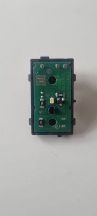
However, I've managed to get hold of an OEM switch (i think its from the drivers door from a Caravelle maybe?) - but have read that those have a 180 ohm resistor in them (and my multimeter shows resistance between two of the pins when the switch is activated) so I assume you cant just wire that in to connect the wires for the existing rear release ? - as they are designed to connect to the can bus?

I was thinking I could wire it into the same pins as the open/close button on the internal bottom of the tailgate - but that is deactivated when the tailgate is shut - so not much use!

The external handle however does both open and close the tailgate however - so that is the ideal one to wire into.

Is the electric tailgate opening switch different to the power latching one? Would it be possible to simply piggy back off the external handle - or does the resistance prevent that from working?


If not, would it be possible to solder part of the PCB in the switch to bypass the resistor ?

Or is it easy to wire this switch into the existing loom somewhere so it works as it would if it was factory fitted?

Anyone done this?


Also - does anyone know where to get the plug for the wires to plug into it? its the same as the electric window switch plug...
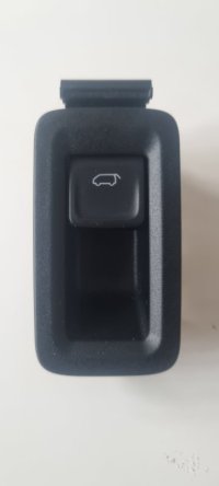
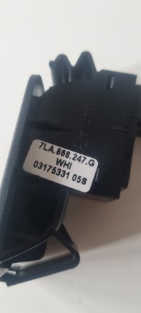
20220523_194318.jpg
20220523_194324.jpg
20220523_194350.jpg
 
Are you sure you don't have a button on the drivers door card to open the rear lid? At the rear of the door pocket.

My Sportline Kombi with power tailgate does.
 
Managed to solder a bit of wire over the 180 ohm resistor so now get continuity across the pins when pulling the switch - so now can install it like any usual switch as per the existing guides...
I had to do the same when I retro fitted a tailgate to my van. It's works fine and it's not possible to open the van when it's moving, which is a nice safety feature.
 
those have a 180 ohm resistor in them (and my multimeter shows resistance between two of the pins when the switch is activated) so I assume you cant just wire that in to connect the wires for the existing rear release ? - as they are designed to connect to the can bus?
Actually the BCM distinguishes the switches inside and outside of the van by this 180 ohm resistance. The switches (0/180 ohm) indeed are wired in parallel.
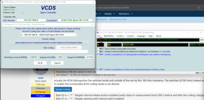
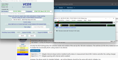
To enable this functionality BCM coding needs to be altered.
Byte 02-6 = "1" : Tailgate internal release button installed (verify status in measurement block 008-3 before and after the coding change)
Byte 01-4 = "1" : Tailgate opening with internal switch enabled
Anyways, the above works for standard tailgate - per wiring diagram should be the same with electric tailgate, too.
 
Managed to solder a bit of wire over the 180 ohm resistor so now get continuity across the pins when pulling the switch - so now can install it like any usual switch as per the existing guides...
Hi Matty, could you actually see the 180 resistor stamp on this one? Is it all working correctly too? So 2 of the pins now act as a shunt releasing the microswitch in the bottom door handle etc?

Thanks Gary
 
Actually the BCM distinguishes the switches inside and outside of the van by this 180 ohm resistance. The switches (0/180 ohm) indeed are wired in parallel.
To enable this functionality BCM coding needs to be altered.
Byte 02-6 = "1" : Tailgate internal release button installed (verify status in measurement block 008-3 before and after the coding change)
Byte 01-4 = "1" : Tailgate opening with internal switch enabled
Anyways, the above works for standard tailgate - per wiring diagram should be the same with electric tailgate, too.

@mmi - Sorry to resurrect an old thread, just wanted to double check that its 180ohm not 180K ohm.

The image looks like its 180K only asking as I'm about to wiring up an internal switch.
 
For those wiser than I..... Am I being daft...... can't find the settings in the BCM?
Any ideas?

1710614221553.png1710614238945.png


1710614285438.png
 
In the coding of your module 09 click directly on the BYTE 01 and 02 and then tick your bits as required.
The labels for these bits are not officially documented in the VCDS yet.
 
In the coding of your module 09 click directly on the BYTE 01 and 02 and then tick your bits as required.
The labels for these bits are not officially documented in the VCDS yet.
cheers, ill go look in a minute, the raised eyebrow was/is that i cant find block 8 at all in adv measurement of "09 central electrics" to check the reading?

But more importantly..... the tick boxes for those bits arent there (unless im missing something - sounds like i might be)
 
oooooooooo, thats a quirk of VCDS, if you use the arrows to scroll to the byte, it doesnt show all the bits!! Lesson learnt!
Any tips for checking the measurements that arent there? - scrap that, took the same approach, typed it in!! Works a treat!

Thanks for the help! for a really small tweak, im really chuffed with this!!
 
Last edited:
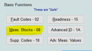
They (ALL) are in the "Meas. Blocks - 08" - not the Advanced..Meas. Values. (which contains just the documented ones).
View attachment 233360
I spotted that too but was a little unclear if I was 100% I the right spot. If you got to advanced and type "008" in the search above the list, you get the 4 x "008" 'readings' and can see the "not installed" reading, afterwards get a "not active/activated" reading when the button is pressed!

The more and more im using VCDS, I'm discovering some of the UI 'features' (quirks)
 
Needless to say, if anyone needs a 180ohm resistor, I now have 99 spare! :rofl:
Hi Mr G,
Could I grab one of these off you?
Happy to reimburse. Have exactly same problem. Switch and housing but no connector or wiring.....

Cheers,
Ash
 
Hello Guys,

Quick question just to be sure I've understood correctly.

On my side I have this as MrG
1732216045111.png
As I can't see 1732216331508.pngI need to change manually the arrowed 0 ( 6th position from the left) by a 1 ?

Thanks in advances for your help !

Nico
 
Hi Mr G,
Could I grab one of these off you?
Happy to reimburse. Have exactly same problem. Switch and housing but no connector or wiring.....

Cheers,
Ash
So sorry I've only just seen this‍♂️ if you need one drop me a DM
 
Back
Top