For Sale Standalone ESP32 BLE Battery Display for Victron Systems

Would be interested to see how people have there's positioned in the van. Are people hard wiring or just usb c cable. Got mine and it works a treat, will be even better once the electrics are upgraded some more
 
RicoPicoUK do you plan on adding software for the app ABC bms? It is used for the very popular sok battery. The app is open source so would you still require a ble capture? Thanks
 
On the victron part for it would it be possible to add something in where if an alarm goes off the screen Jumps to the “page” of the connected device with what the alarms is about?
 
This looks very nice! Is there an idiot's guide to doing an initial firmware load onto a new device?

Hi Andrew,

Not so much of an idiots guide, I will try and help out where possible.

Step 1 - Power the device. - You can power via USB-C or from one of the rear power cables.
If you use rear power cable, you need to press a reassessed button on side of the device to get it to boot.

Step 2 - go into menu, - 3 dots on bottom.

Step 3 - Enable Wifi

Step 4 - find the wifi hotspot named ChargeScreen, - you can use your phone or mac/pc.
The hotspot hopefully will automagically open up the page, but if it doesn’t - the address of the device is http://192.168.4.1 - enter this into a web browser.

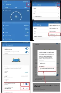
Step 5 - Select the devices you own, after you select the devices, if the device needs a key, then it will spawn a box to enter the key.

You can get victron keys as per the image.

Step 6 - Click Save at the bottom of the page.

Untitled.webp
 
Having received my ChargeScreen and 12V step down cable at end of last week, I am working on a 3D printed design . . .

IMG_3508.webp

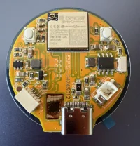
. . . the first step was to accurately capture all of the dimensions of the screen, the PCB outline and key components. Now this is completed and proven the next step is to design mounting and hidden cable exit points for the back, plus a solution for that pesky power button on the side.

IMG_3509.webpIMG_3510.webp

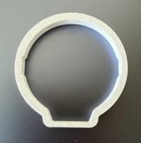
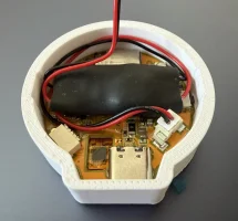
My current thinking is to embed the step down voltage cable/PCB in the back of the case, so there is just a pair of 12V DC & Ground cables exiting out of the rear. For fixing I think one or two simple counter sunk hole(s) to allow for a 13mm screw.

I am open to suggestions, if anybody would like to submit their ideas too . . . maybe a metal washer imbedded in the back to allow easy attachment to a magnetic phone mount.

 
Last edited:
Having received my ChargeScreen and 12V step down cable at end of last week, I am working on a 3D printed design . . .

View attachment 331567

. . . the first step was to accurately capture all of the dimensions of the screen, the PCB outline and key components. Now this is completed and proven the next step is to design mounting and hidden cable exit points for the back, plus a solution for that pesky power button on the side.

View attachment 331568View attachment 331569

My current thinking is to embed the step down voltage cable/PCB in the back of the case, so there is just a pair of 12V DC & Ground cables exiting out of the rear. For fixing I think one or two simple counter sunk hole(s) to allow for a 13mm screw.

I am open to suggestions, if anybody would like to submit their ideas too . . . maybe a metal washer imbedded in the back to allow easy attachment to a magnetic phone mount.
IMG_3511.webp

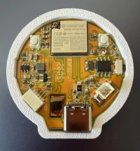
. . . it seems to fit quite nicely.
 
Are you able to add Ruuvi temp sensors, they currently integrate with victron cerbo. Also I have some Bluetooth tire pressure sensors is that an option?

Cheers
 
Back
Top