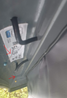
Is my solar setup faulty?

I've got that same 250w panel (albeit with version with the junction box on the back) and it's been excellent for me. Having to buy a another victron mppt seems a bit annoying, I assume that's because the one you have can't handle that panel? Definitely check because you don't want to have to buy a new one for nothing.

Avoiding drilling the panel again might actually be a bit tricky, from the photos it looks like your existing panel goes right to the back of the roof? If you install the panel forward of the existing one, you'll leave a pretty messy patch where they've removed the existing one from but if you cover it, I'm not sure how you'll get the cables down without going through the panel again. A panel with a back junction box would solve the issue but that version of the one you've linked to appears out of stock - plus it involves cutting a really big hole in the roof! Have a look around the options and see what's out there, ideally I'd say you want something to entirely cover the mess made by removing the existing one, with a compact back fitting you can stick back through the roof easily.
 
Thats a serious package! Both are highly recommended.
For your cables, I've used this kind of thing, not pretty but they do the job.
Roof Gland 2 Cable Entry To Solar Satellite Aerial Aircon Motorhome Caravan Boat | eBay

Thanks for the cable entry link. I would need to try and find a black version of that to match up with the van, but I know what I am looking for now.

As @t0mb0 points out, I may have an issue here, as to avoid drilling through the new panel, we would have to mount it further forward, which would likely leave a mess where the old one used to be! Nothing ever simple is it?
 
I've got that same 250w panel (albeit with version with the junction box on the back) and it's been excellent for me. Having to buy a another victron mppt seems a bit annoying, I assume that's because the one you have can't handle that panel? Definitely check because you don't want to have to buy a new one for nothing.

Avoiding drilling the panel again might actually be a bit tricky, from the photos it looks like your existing panel goes right to the back of the roof? If you install the panel forward of the existing one, you'll leave a pretty messy patch where they've removed the existing one from but if you cover it, I'm not sure how you'll get the cables down without going through the panel again. A panel with a back junction box would solve the issue but that version of the one you've linked to appears out of stock - plus it involves cutting a really big hole in the roof! Have a look around the options and see what's out there, ideally I'd say you want something to entirely cover the mess made by removing the existing one, with a compact back fitting you can stick back through the roof easily.

The good news with the MPPT, is that the converter said (lets see if he actually does it) he would take it back as stock and refund me on it, so I wouldn't be out of pocket. The current MPPT is 10A, so would not be sufficient for the new panel, I would need to the 20A one. But, thats fine if he is having the 10A one back.

The bad news, as you point out (and I knew but had forgot) is that if he mounts it further forward to avoid drilling the new panel we are left with the mess where the old one was. This is a better picture of the mounting of the existing panel, as you say, its right at the back, just on short of the lip of where the roof curves.

1610215819196.png

From below, you can see the cables enter at this point

1610215892182.png


I dont like the idea of drilling a huge hole in the roof to fit a new panel to be honest. I did have another couple of ideas, but not sure if they would work / be appropriate and would appreciate some feedback.

Forgive the rubbish diagram, but hopefully it illustrates the ideas.

1610218507200.png
So, new panel covers where old one was including the old holes (black circles).

I have two ideas of where new holes could be.
  • Same horizontal line as the original holes (black circles) but either side of the panel and not through it. So flat on the roof either side of panel. They would be a distance apart so I guess I would need a "single cable entry" box for each hole?
  • Same vertical line as the original holes (black circles), but that would mean they went through the curved bit of the roof further toward the back (so would be lower than current if you look at the external cable entry photo above). Not sure if that would work or cause issues when the roof closes?
Do either of those ideas sound viable? Or am I getting in to different types of issues if I go down one of those roads?

Thanks

1610216527804.png

1610216907261.png
 
Last edited:
I would explain your concerns and get them to remove the old panel and at least have a go at cleaning up the rear few inches as best they can, to see if the panel can possibly go forward so you can use the existing holes without drilling the new panel. Worth a try before giving in and drilling more holes.
 
BEFORE the old panel is removed, get the converters to disconnect it where it connects to your solar controller and connect another panel temporarily.

Lay the new panel next to the van in sunshine and this will prove if the existing panel is the problem,
If same fault is still there connect YOUR panel to a new controller temporarily connected to your battery with existing wiring.

This should show if the fault is, 1 the panel
2 the solar controller
3 the wiring from your battery to solar setup.

It would be crazy to remove old panel from your roof unless it is proven 100% to be the problem.
These are the steps I would take before attacking your roof panel.
 
I would explain your concerns and get them to remove the old panel and at least have a go at cleaning up the rear few inches as best they can, to see if the panel can possibly go forward so you can use the existing holes without drilling the new panel. Worth a try before giving in and drilling more holes.

100% agree @Phil_G, that is the best bet - if the roof can be cleaned up, the new panel mounted a few inches forward and re-use existing holes that would be definitely be best. I am just trying to come up with a viable plan B, just in case the roof does not clean up well and he has to stick the new panel over the old holes (dont want him drilling the panel again). As you say, we wont know until he takes the old one off, but just want to ensure I can mount the new panel (one linked above) using new holes in a worst case scenario!

If the hole options I suggested on the post above wouldn't work, be good to know. I am keen to use the panel I linked above if possible (as opposed to one which needs a larger hole), but of course I don't want to be stuck with a panel I cant mount at all if the roof doesn't clean up.

Thanks.
 
Agreed. If conditions didnt change, a sudden drop from 26v to 14v indicates an intermittent panel.
To prove its not the controller, just poke your voltmeter probes into the solar input screws - if the meter and the controller agree its 14v, then it has to be an intermittent panel. I'd even rule out a bad joint on the way to the panel, since your panel voltage seems to be around 25v when the fault is clear, OR around 14v when the fault is present. It seems not to vary as might caused by an oxidised joint, but seems to alternate between specifically 25v and 14v, which suggests faulty interconnects within the panel (which they drilled ;) )

Hey @Phil_G,

I managed to catch it going wrong again today and had already set up my (ancient) multi-meter ready to do the test you suggested above (check the volts from the solar panel at the point the issue occurs, and see if it agrees with the Bluetooth, at a figure around 13v / 14v). So, this is what I found...

1610372752269.png

Just to make sure I was measuring the right thing, this is where I stuck the multi-meter pins to get that reading.

1610373054894.png

You cant see it very well, but its in the + and - for the inputs marked "pv".

Incidentally, when the solar is working properly (panel showing around 23v - 26v on Bluetooth), the multi-meter also agrees.

So, based on your comments above, this proves it is the panel that is the issue, as opposed to the MPPT?

Thanks.
 
Not completely, but thats what it suggests. The victron can't do anything with 14v. ;)
To eliminate wiring faults you could measure at the panel. Take two ordinary sewing pins and
poke one into each cable between the panel box and the drilled holes on the roof, ie through the plastic insulation.
You might need pliers. Measure the 14/24 volts there, if you see 14 then the panel is duffinitely def.

IMG_20210111_234608.jpg
 
Last edited by a moderator:
We may have already asked this but are your black cables from solar and mppt going to the same ground point as your negative cable from battery .
And is it a good connection with no resistance to ground as you can get weird faults when grounded at different points and resistance reading in ohms between them.
 
Not completely, but thats what it suggests. The victron can't do anything with 14v. ;)
To eliminate wiring faults you could measure at the panel. Take two ordinary sewing pins and
poke one into each cable between the panel box and the drilled holes on the roof, ie through the plastic insulation.
You might need pliers. Measure the 14/24 volts there, if you see 14 then the panel is duffinitely def.

View attachment 98389

Oh, I like the needle trick! I’ve never seen that before...
 
We may have already asked this but are your black cables from solar and mppt going to the same ground point as your negative cable from battery .
And is it a good connection with no resistance to ground as you can get weird faults when grounded at different points and resistance reading in ohms between them.

Hi @AussieMick,

So, my lack of electrical knowledge will be all to clear again with this answer, but I will do my best.

From solar: I can only see two cables from the solar, both of which go directly into the MPPT controller (black cable from the solar does not go anywhere near the battery / common earth point as far as I can tell).

From MPPT: Two cables from the MPPT, red and black. Both bolt directly to the appropriate terminal post on the battery.

You can see all of the cables on the negative terminal here in the picture below, one of the thicker ones is the one which comes from the MPPT

1610446875014.png

Here is a pic of the MPPT and battery, so you can see wires to and from MPPT (there are only 4, 2 in from solar panel, 2 out to battery - thats it)

1610447049989.png

I am not 100% sure if that is the info you asked for. Please let me know if not.

Thanks
 
One more question
Is your leisure battery negative terminal connected to the vw ground point under drivers seat or another spot that has almost 0 ohms to the vw ground point under drivers seat. 0.2 ohms is ok. Measured with a multimeter on ohms scale.
Or do all negative return cables connect to negative battery terminal and battery terminal is not grounded to van ground point.
+ 1 more
Are the cables going into your mppt nice and tight and no loose strands hanging out that could touch a neighboring terminal.
 
Last edited:
One more question
Is your leisure battery negative terminal connected to the vw ground point under drivers seat or another spot that has almost 0 ohms to the vw ground point under drivers seat. 0.2 ohms is ok. Measured with a multimeter on ohms scale.
Or do all negative return cables connect to negative battery terminal and battery terminal is not grounded to van ground point.

I am 99% sure nothing connects from the battery to under the drivers seat.

I am 90% sure that "all negative return cables connect to negative battery terminal and battery terminal is not grounded to van ground point." but I will check that and let you know if I am wrong. But as I understand it now, there is no ground from the battery.

+ 1 more
Are the cables going into your mppt nice and tight and no loose strands hanging out that could touch a neighboring terminal.
I can confirm there are no loose strands of wire at all in that area. I all looks well insulated and attached properly.

Finally, in case it helps:

To detect the problem I have to connect the Bluetooth app to view the figures at that specific point in time. Many times I connect the app it looks fine (reasonable watts based on sun and 23v-26v), but at other times its down to 0W and 13v-14v (even though its sunnier that it was when it was last working, and the battery is well below charge level). It switches between working and not working on its own during the day, even if you do not go near the van. Yesterday, the van was on the drive all day (never even opened it). Every hour or so I connected to the Bluetooth (from inside the house) and witnessed the issue on 3 separate occasions (0W and 13v-14v). On one occasion, I was actually connected to bluetooth app when it flicked from "not working" to "working" - nothing happened to trigger it (e.g. sun came out brighter, or battery mode changed), it just flipped for no perceivable reason.

Thanks
 
Not completely, but thats what it suggests. The victron can't do anything with 14v. ;)
To eliminate wiring faults you could measure at the panel. Take two ordinary sewing pins and
poke one into each cable between the panel box and the drilled holes on the roof, ie through the plastic insulation.
You might need pliers. Measure the 14/24 volts there, if you see 14 then the panel is duffinitely def.
Seems a neat trick, I will try this when I get the van back. To add to my woes someone slid into the back of my camper over xmas, so it goes into repair shop for a new tailgate today, so will be without it for about 1 week. I will try this trick when it's back just to 100% piece of mind.

I'd even rule out a bad joint on the way to the panel, since your panel voltage seems to be around 25v when the fault is clear, OR around 14v when the fault is present. It seems not to vary as might caused by an oxidised joint, but seems to alternate between specifically 25v and 14v, which suggests faulty interconnects within the panel (which they drilled ;) )
I had read the above comment as it is not the cables (so either panel or MPPT). That said, I think your neat "pin trick" would eliminate all other possibilities!

One question. I assume when you get a new panel it comes with cables attached. So, when he swaps the panel and MPPT for the better specification ones, the wires from panel to MPPT would be swapped for new ones as part of that process?
 
Not completely, but thats what it suggests. The victron can't do anything with 14v. ;)
To eliminate wiring faults you could measure at the panel. Take two ordinary sewing pins and
poke one into each cable between the panel box and the drilled holes on the roof, ie through the plastic insulation.
You might need pliers. Measure the 14/24 volts there, if you see 14 then the panel is duffinitely def.

View attachment 98389

Hey @Phil G and others.

I got the van back yesterday eve (following an accident repair) and was able to perform the test you suggested with the pins, and here are the results. I have results for when the panel was working as expected (23V), and also readings for when the panel hit the 0W 14V issue. Both readings were taken within 5 minutes of each other (again, as always there was no change in the sun conditions or the battery condition) Here are the results:

Panel working OK, showing 22.8V

1611404243473.png

Panel NOT working properly showing 14.01V

1611404371146.png

I inserted the pins in the solar panel wires very close to the panel itself, just as they go through the roof - so the pins are within 6 inches of where the cables leave the panel (and there are no connections between the panel and where the pins are, its just the cable straight from the panel. Here are where the pins go into the cables.

1611404507199.png

Conclusions

So, we can see from the pics that the voltage on the multi-meter is less than the corresponding voltage shown on the app - I suspect that is due to the fact that my pins are not making a brilliant connection.

We can see that when the panel is working OK the Bluetooth shows 22.8V and the multi shows 17.8v. When the intermittent fault kicks in, we see the Bluetooth shows 14V and the multi-meter reading drops to around 9.7v.

Would you agree that this now shows it is the panel at fault? As when the intermittent issue kicks in, we see big voltage drops both on the Bluetooth display AND the multi-meter (which is reading from the wires right next to the panel).

The camper is going back to the converter AGAIN to hopefully get everything replaced with the panel and MPPT II linked in the posts above. So would be good to get confirmation asap that the results from this test show its the panel that is faulty.

Looking forward to hearing back. Thanks again for all your help.

Many thanks.
 
Is your multimeter battery drained? Just that each multimeter reading differs by approx 4/5v. A duff battery sometimes throws up errors like that I have found.
 
Is your multimeter battery drained? Just that each multimeter reading differs by approx 4/5v. A duff battery sometimes throws up errors like that I have found.

Thanks @oldiebut goodie, I think the multi-meter battery is ok, when I used it the week before to measure the voltage at the MPPT, it corresponded 100% with the voltage on the Bluetooth screen. On that occasion I could get the ends of the multi-meter pushed well onto the MPPT connectors, so had a really good connection when readings were made. The difference this time, is the use of the pins pushed into the wires. It was hard to get the pins in, so I suspect the pins are through the insulation and on the wires inside, but have NOT made a brilliant connection - which I am guessing could account for the disparity between the Bluetooth reading and that at the multi-meter?

I am hoping that the important bit, is that when the panel goes into intermittent fault mode (as seen on the Bluetooth screen with the voltage drop), we ALSO see the multi-meter voltage reading drop proportionally to the Bluetooth reading. I am assuming means that the fault is with the panel, as opposed to some dodgy connection in the wires nearer the MPPT (if it were an issue with the connections lower down, I am expecting I would have seen a drop in the Bluetooth, but NOT in the multi-meter reading). That's the bit I wanted to get confirmed. Does seeing that corresponding voltage drop on the multi-meter at the time of the fault, prove its the panel that's the issue.

Thanks.
 
I would say so, but if you're going to use those pics as ammo then you need to fix your meter first ! :)
A digital multimeter has an extremely high input impedance (many MΩ) and your connection via the pins should be either there or not, a few ohms even kΩ wont make any difference to the voltage. As Oldie says, there seems to be something amiss with the meter. Do you have another one?
 
Last edited by a moderator:
Measure a known voltage to check the meter. Could just measure at the actual mppt battery connection to see if it agrees with the mppt reading.
 
When you say that the panel is working in first picture why is the current reading so low, .5 amp and only 12w
Is your battery nearly full when you made this test.
If it was , that will affect your solar readings . Try it with a battery that is less than 80%, then your battery will want all that the panel can output.

Simple Test for your converter before panel is removed from your roof.

Unplug your panel from Mppt and temporarily connect replacement panel next to your vehicle in sunshine and check readings. Not with a fully charged battery though or it will go into float mode quickly which will give you low current and wattage readings as the mppt tapers off input from panel to battery.
Screenshot_20210119-152851.jpg l would expect current and wattage readings a bit like these when your panel is in the sun. This is with a victron bmv712 measuring across the positive battery terminal and the shunt and with a 200w panel.
 
Back
Top