Is my solar setup faulty?

When you say that the panel is working in first picture why is the current reading so low, .5 amp and only 12w
Is your battery nearly full when you made this test.
If it was , that will affect your solar readings . Try it with a battery that is less than 80%, then your battery will want all that the panel can output.

Simple Test for your converter before panel is removed from your roof.

Unplug your panel from Mppt and temporarily connect replacement panel next to your vehicle in sunshine and check readings. Not with a fully charged battery though or it will go into float mode quickly which will give you low current and wattage readings as the mppt tapers off input from panel to battery.
l would expect current and wattage readings a bit like these when your panel is in the sun. This is with a victron bmv712 measuring across the positive battery terminal and the shunt and with a 200w panel.

Hey @AussieMick,

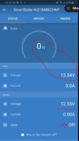
The battery was probably about 75% charged at the point I took the screen shots on the previous post. Answering your specific question, the reason it was only 12W is it was dull at the time the test was done (cloudy, not much sun). I guess this proves that "when the panel is working" even in dull conditions, it does actually pull something, even if it is low watts. The second shot is showing (when the intermittent fault occurs), that in the same conditions (still dull, battery only 75%), it drops from 12W to 0W and 23v to 14V, and does so for no reason. I have seen the exact same thing happen from 60W and 26V, just drops to 0W and 13V for no apparent reason (even though battery is not charged). When you look at the MPPT the next day, you can see the panel did not spend any time at all in ABS or FLOAT modes on the previous day.

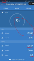
Here is another example from a different day. This screen shot was taken in the middle of the day in decent sun. 20 minutes before the screen shot below the display was showing 50W and 26v.
1611660673047.png

The charge state is shown as "off" as opposed to "float or abs". Taking the charge status shown, together with the leisure battery voltage being 12.55v I am assuming that means the leisure battery is NOT fully (or close to being fully) charged? I cant see any reason why it just drops to 0W and 13v. It does it multiple times a day, with different sun conditions, and with the leisure battery in different stages of charge (never does it read ABS or float when I see these drops).

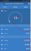
Just as a comparable, I have just gone outside now and checked, and it is "working at the moment". The conditions now are much duller than they were when the above screenshot was taken. Also, the leisure battery is showing a much higher level of charge (13.4v as opposed to 12.5 in pic above).

So, despite today being dull and battery being at 13.4v it is charging and in "bulk charge mode" vs shot above (which shows the issue), which was taken on a brighter day, when the leisure battery had far less charge.
1611660950534.png

Not sure I am explaining it well. Does what I am saying make sense? I.e. that there is an intermittent issue when it drops to 0W and 13v for no reason (as far as I can tell). It does so intermittently and there is no specific pattern. I.e. it does not occur just when the leisure battery hits a certain charge, or when the sun is strong or its dull, there does not seem to be a pattern.

Thanks
1611660528985.png
 
I would say so, but if you're going to use those pics as ammo then you need to fix your meter first ! :)
A digital multimeter has an extremely high input impedance (many MΩ) and your connection via the pins should be either there or not, a few ohms even kΩ wont make any difference to the voltage. As Oldie says, there seems to be something amiss with the meter. Do you have another one?

Thanks @Phil_G, @t0mb0 and @oldiebut goodie.

Sorry for the late response, but the weather (snow etc.) has been a shocker where I am, so never made it out to the van.

So, as for this multi-meter connected to the "pins" not matching the reading from the Bluetooth.... The suggestions were:

1. Try another meter if you have one
- i dont have another one unfortunately

2. Check the battery on the original meter, as that could impact voltage reading / 3. check meter against known source

So, when I took the meter in after the last test, i always remove the battery (as they tend to leak when stored I find). So after you suggestion I popped the battery back in and have gone to the van measured a known voltage (measured leisure battery and the voltage going into the MPPT). Both of those tests did match between the Bluetooth and the multi-meter, so I am not too sure what happened with the pin test not matching.

I read your point about it being a poor connection wont matter, but thought I would point out that the meter in question in absolutely ancient. I would guess it is probably 40 years plus old (was my fathers, who was an electrician). I still works fine (used it on things inside the house), but not sure if more sensitive to poor connections as so old?

When the snow is off the top of the van I shall have another go with the pins and see if I can get a better match.

Roy
 
I would say so, but if you're going to use those pics as ammo then you need to fix your meter first ! :)
A digital multimeter has an extremely high input impedance (many MΩ) and your connection via the pins should be either there or not, a few ohms even kΩ wont make any difference to the voltage. As Oldie says, there seems to be something amiss with the meter. Do you have another one?

Hi @Phil_G, @oldiebut goodie and @AussieMick.

OK, so I managed to repeat the voltage test where I put pins in the wires near the panel and test voltage at that point. If you remember, last time the multi-meter had a different reading to the Bluetooth. I replaced the battery and tested it on a known voltage first and it was all good, and then i repeated the test.

How I performed the test

Pins in cables near the panel

1611939025328.png

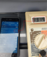
Reading when panel was NOT working, (in the 0W 13v error state) - both meter and Bluetooth show same voltage of 13.19v. Note. the low voltage of leisure battery at 12.4v which is clearly well below 100% and thus it should be charging.

1611938925320.png

2 hours later, I took Reading when panel was working again, both meter and Bluetooth show similar voltage around 21.5v.

1611938746311.png

Conclusions:
We now have readings that match from the meter and Bluetooth (which I never had last time)

I am concluding that as the meter is connected to the pins very close to the panel, and it shows 13v when the panel is in error mode - that this proves that it is the panel which is fault. I.e. that it is NOT an issue with the wiring between the panel and the MPPT, but is actually an issue with the panel itself.

Would you guys agree with that conclusion?

Many Thanks
 
Disconnect the panel from the victron mppt controller and follow the procedure in this webpage..
 
Hi @Phil_G, @oldiebut goodie and @AussieMick.

OK, so I managed to repeat the voltage test where I put pins in the wires near the panel and test voltage at that point. If you remember, last time the multi-meter had a different reading to the Bluetooth. I replaced the battery and tested it on a known voltage first and it was all good, and then i repeated the test.

How I performed the test

Pins in cables near the panel

View attachment 100641

Reading when panel was NOT working, (in the 0W 13v error state) - both meter and Bluetooth show same voltage of 13.19v. Note. the low voltage of leisure battery at 12.4v which is clearly well below 100% and thus it should be charging.

View attachment 100640

2 hours later, I took Reading when panel was working again, both meter and Bluetooth show similar voltage around 21.5v.

View attachment 100639

Conclusions:
We now have readings that match from the meter and Bluetooth (which I never had last time)

I am concluding that as the meter is connected to the pins very close to the panel, and it shows 13v when the panel is in error mode - that this proves that it is the panel which is fault. I.e. that it is NOT an issue with the wiring between the panel and the MPPT, but is actually an issue with the panel itself.

Would you guys agree with that conclusion?

Many Thanks

I agree with the conclusion, I think you’ve done as much as you reasonably can to demonstrate the panel is faulty.
 
Take note of the bit at the end of that page..

And if you are testing a charge controller you will need to make sure that the battery is NOT fully charged otherwise it will not be able to accept current.

The first two measurements use the solar panel on its own. When disconnecting the solar panel, regulator and battery, take care to disconnect the panel from the regulator first, and then disconnect the regulator from the battery. When reconnecting, connect the regulator to the battery first, and then connect to the solar panel. This will avoid causing damage to the regulator.
 
I would suggest its conclusive without the need to go any further - even with a very low battery the controller won't load it below its MPP so will never pull the panel down to 13 volts. With a full battery the panel voltage should be above the MPP towards 21 volts.
Its a faulty panel.
Cheers
Phil
 
I would suggest its conclusive without the need to go any further - even with a very low battery the controller won't load it below its MPP so will never pull the panel down to 13 volts. With a full battery the panel voltage should be above the MPP towards 21 volts.
Its a faulty panel.
Cheers
Phil

@Phil_G, @t0mb0, @Dilbert, @Grim Reaper

First up, a HUUUUGE thanks to all of you for taking your time and patience in guiding me through this diagnosis process.

The converter (thanks to all your help) has now accepted there is an issue and is willing to replace the panel and MPPT.

I have two last questions, and then I promise to leave you all alone! :)

Firstly, before I pull the trigger on my replacement panel and MPPT, can I ask you to cast your eye over the two one last time and just confirm the panel and MPPT are compatible (i.e. the MPPT is sized correctly to make full use of the 250W panel).

The two products are:.

1612033402815.png

and

1612033350497.png

Are these two products properly matched? Would hate to make a mistake now on the replacement parts!


And lastly, based on the diagnosis we have done on the old setup we have proven that the panel is faulty. Have we also proven that the original 10A MPPT (the one currently fitted) is OK, or could that also be faulty?

Thanks guys - you are life savers!
 
Without testing with a good input you can't tell, can you test with another panel?
It won't be any good for the 250W panel but you could sell it if the converter doesn't keep it as part of the deal.
 
Are these two products properly matched?

The two parameters you need to look at are [1] the solar panel open circuit voltage and [2] the solar panel short circuit current. These are your extreme values.
  • Open circuit voltage: 34.9V
  • Short circuit current: 9.2A
The MPPT controller you have linked will easily do this. You could save some money (assuming you are paying the difference) by selecting the 75V 15A MPPT controller: Midsummer Energy

I am assuming that with a 250W panel on the roof you will not be looking to expand any further!

EDIT: Whoops! SORRY. My error. I ignored the max power. Your selection is correct. Victron SmartSolar 20A 100V MPPT.
 
Last edited:
The Victron SmartSolar 75/10 has a max PV wattage of 145W, the new panel is 250W

Edited to add that Victron has a 5 year warranty.
 
I would suggest its conclusive without the need to go any further - even with a very low battery the controller won't load it below its MPP so will never pull the panel down to 13 volts. With a full battery the panel voltage should be above the MPP towards 21 volts.
Its a faulty panel.
Cheers
Phil

Hi all,

The van is now back with the converter to fit the new panel and MPPT. I asked him NOT to drill the panel (to allow the cables to go through), but based on the photos he has sent me, it looks like that will be unavoidable (the old panel did not come off clean, so if the new one is mounted further forward to avoid drilling, it will show unsightly marks from where the old panel was). On the positive side, he sent me a picture of the fitting instructions which say you are allowed to drill the panel without voiding the warranty as long as you follow their guidance. This is what it says...

1613115011072.png

There are two conditions
1. Drill 12mm from solar cells
2. Properly sealing the any edges exposed by drilling.

We are fine with the first condition (the holes would be about 53mm from the nearest cell, so much more than the 12mm rule), but I am more concerned about the sealing bit.

With regard to the sealing of the panel where he is going to drill it, is there anything specific I should ask him to do?

This is the new panel placed on the roof - I have put red dots where I estimate he would drill....

1613115269853.png

Any advice appreciated on how to seal the holes he drills appreciated. I am of course keen that after all this I dont end up in a position in 12 months time where the panel is ruined due to water getting into the panel via those drill holes.

On the previous panel (now removed), he sealed it as in the photo below - I assume he would do the same again unless I ask for something different.

1613115563106.png

Any advice appreciated re sealing around the holes / cable entry points.

Roy
 
Presumably he'll cut off the connectors & drill just for the cable... if he's attaching it with Sikaflex, thats also a perfectly good sealant :thumbsup:

Hey @Phil_G,

All I have to go on is what is in the photo (he sent me a WhatsApp, not actually seen it in person). When hit fitted the previous panel, he did as you suggested, the holes drilled were just for the cable (no big holes for the connectors as well). The cable then entered in the back of the van and went off behind a panel (which is where I assume he did the connections).

I can mention the Sikaflex sealant stuff to him (assume you mean something like this: Sikaflex 522 Caravan Sealant) - thanks for that. I guess it also gives me some confidence that if he does it, and in 12 months the seals does not look great when the cable enters, I could always re-do it myself with some of that Sikaflex stuff?

Thanks
 
Hi,. Sorry but very late to the party here. We had exactly the same problem with a midsummer 150w panel after about a year, the problems started after a very hot summer( Not sure if it was exactly the same model as yours) When it was in full sun and warming up, the internal micro connections in the panel were separating and the panel voltage dropped to only half what it should. Eventually Mid summer acknowledged the problem and said it was an issue with the panels they were getting so had taken it up with the manufacturer. They did send us a replacement panel without warranty but we chose to go with a slightly larger (dimensions and power) and reportedly more reliable panel supplied by our convertor (the original came with our Skyline roof). So far so good and it has functioned in much hotter conditions than the previous one and survived. Hope you get it sorted out.
 
Hi all,

Good news! I have had the camper back from the converter and I have had the following fitted (to replace the old / faulty parts).

  1. Photonic Universe 250W panel (12V solar panels charging kits for caravans, motorhomes, boats, yachts, marine)
  2. Victron MPPT 20A 100V (Midsummer Energy)
  3. Victron 500A Smart Shunt (Midsummer Energy)
    1. Shunt fitted with temperature sensor (Midsummer Energy)
  4. 12V 110AH Xtreme AGM Leisure Battery (XR1750) NCC Class A (12V 110AH Xtreme AGM Leisure Battery (XR1750) NCC Class A - Alpha Batteries)
The converter never setup the Victron Connect App properly to configure the MPPT or SmartShunt. I have now done this and made a couple of changes which seem to be fine, namely:

  1. Changed the setting on the SmartShunt so it recognises the aux input as a temperature sensor. The now shows fine in the app so is working
  2. Setup a Victron network and joined both the MPPT and Smart Shunt to that network, so they can share data. This seems to work OK, as I can now see the temperature from the SmartShunt displayed on the screen when I connect to the MPPT (showing the MPPT is getting that data from the SmartShunt via the network).
So, on the face of it, it is all working ok (although I only had it back yesterday, and it has rained ever since, so cant see at this stage how well it works).

I do have a couple of questions about the settings in the Victron Connect app for both the MPPT controller and the SmartShunt - just to make sure that the default settings they have are appropriate for my setup (battery / panel etc).

I will ask those questions as two separate posts below, as I appreciate some people will know about the MPPT and others about the SmartShunt.

Thanks in advance.

Victron SmartSolar MPPT 20A / 100V - setup questions

So, I have looked at the instruction manual for the MPPT controller and it says to ensure that the settings configured are appropriate for your specific leisure battery. The battery fitted is a 12V 110AH Xtreme AGM Leisure Battery (XR1750) NCC Class A. I have had a google on this, but not really got anywhere with it. I am hoping someone on here can either confirm that the default settings are fine, or give me an idea as to what they should be. These are the settings for the MPPT controller:

1613897427976.png

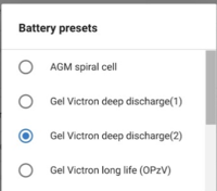
It looks like most of the settings (Charge Voltages etc.) are set by either selecting a Battery Preset (see options below), or by selecting "expert mode" and specifying your own numbers for the Charge Voltages. The "factory default" seems to be the Gel Victron Deep Discharge option.

The other Battery Preset options available are:

1613897646698.png
1613897671612.png

Having gone through all of this to get a decent setup, I am keen to get these settings correct, so I dont end up damaging the battery, and ensure it all works as well as it can.

So, my question are:
  1. Are the Factory Default settings ok for my specific battery? Or should I change them?
  2. If I need to change them, then:
    1. Should I pick another pre-set, if so which one?
    2. Should I use expert mode and set the Charge Voltages manually? And if I do, what numbers should I use?
  3. What does the "equalisation stuff" do, and do I need to worry about it?
Thanks again everyone!
 
Hi all,

Good news! I have had the camper back from the converter and I have had the following fitted (to replace the old / faulty parts).

  1. Photonic Universe 250W panel (12V solar panels charging kits for caravans, motorhomes, boats, yachts, marine)
  2. Victron MPPT 20A 100V (Midsummer Energy)
  3. Victron 500A Smart Shunt (Midsummer Energy)
    1. Shunt fitted with temperature sensor (Midsummer Energy)
  4. 12V 110AH Xtreme AGM Leisure Battery (XR1750) NCC Class A (12V 110AH Xtreme AGM Leisure Battery (XR1750) NCC Class A - Alpha Batteries)
The converter never setup the Victron Connect App properly to configure the MPPT or SmartShunt. I have now done this and made a couple of changes which seem to be fine, namely:

  1. Changed the setting on the SmartShunt so it recognises the aux input as a temperature sensor. The now shows fine in the app so is working
  2. Setup a Victron network and joined both the MPPT and Smart Shunt to that network, so they can share data. This seems to work OK, as I can now see the temperature from the SmartShunt displayed on the screen when I connect to the MPPT (showing the MPPT is getting that data from the SmartShunt via the network).
So, on the face of it, it is all working ok (although I only had it back yesterday, and it has rained ever since, so cant see at this stage how well it works).

I do have a couple of questions about the settings in the Victron Connect app for both the MPPT controller and the SmartShunt - just to make sure that the default settings they have are appropriate for my setup (battery / panel etc).

I will ask those questions as two separate posts below, as I appreciate some people will know about the MPPT and others about the SmartShunt.

Thanks in advance.

Victron 500A Smart Shunt - setup questions

So, I have looked at the instruction manual for the Smart Shunt and it says to ensure that the settings configured are appropriate for your specific leisure battery. The battery fitted is a 12V 110AH Xtreme AGM Leisure Battery (XR1750) NCC Class A. I have had a google on this, but not really got anywhere with it. I am hoping someone on here can either confirm that the default settings are fine, or give me an idea as to what they should be. These are the settings for the Smart Shunt:

1613898012896.png

All of the figures down to "Time-to-go average period" can be changed. I have set the Battery capacity to match the actual battery being used (setting was 200AH by default), but for the others I have no idea if they are appropriate for my specific battery (12V 110AH Xtreme AGM Leisure Battery (XR1750)). Do I need to change any settings?

Finally, when I know the battery is 100% I want to click the "Synchronise" button. My question here is, do I need to wait for the battery to be at rest (so the voltage has settled), i.e. a couple of hours after dark, or can I just click it during the day when it is in "float mode" (when the voltage would be higher)?

Thanks in advance for the help!
 
Back
Top