You are using an out of date browser. It may not display this or other websites correctly.
You should upgrade or use an alternative browser.
You should upgrade or use an alternative browser.
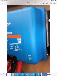
looks like you have an isolated version . . . same as me.
have you got BOTH NEG terminals connected to ground,
so TWO positives and TWO negatives . . .

see here for mine . .

 www.t6forum.com
.
have you got BOTH NEG terminals connected to ground,
so TWO positives and TWO negatives . . .

see here for mine . .

[Guide] DC-DC Charger (for leisure battery) -- How I Done It --
DC-DC Charger (for Leisure battery) -- How I Done It -- ************************************************** Dellmassive`s -- "how I Done It" -- Thread ************************************************** Kit List And Stuff -- How I Done It & What I Use --...
.
also see here about settings . .
 www.victronenergy.com


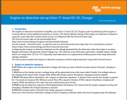
(Re)start level: The default setting (13.3V) is based on generic smart alternator setup. Most smart alternators will generate 13.5V when the engine is running, and regular alternators will normally generate >14V. In an application with a regular alternator the restart level can therefore be set to a higher value, e.g. 14V. Shutdown level: The default setting is 13.1V. this creates a hysteresis between the restart level and prevents excess discharge of the starter battery. Shutdown level range: 12|12; 12|24 models: 8 to 17V 24|12; 24|24 models: 16 to 35V Setup input voltage lock-out: Input voltage lock-out is the minimum level at which charging is allowed, below this level charging stops immediately. To determine this setting two criteria are important: • Minimum alternator voltage: A smart alternator can (temporarily) operate at very low alternator voltage (<12.5V) e.g. when the vehicle accelerates. This low voltage is allowed within the one-minute delay during the “engine on detection sequence 23”. If charging must remain active during this period, the lock-out level must at least be set below the minimum alternator voltage. Note: If this low voltage period exceeds the one-minute timer charging will be disabled on engine shutdown detection. • Voltage drop across the input cable: As seen in “engine on detection sequence 12”, VIN is lowered by Vcable due to the input current. The voltagedrop at Vin caused by Vcable must not trip the voltage lock-out. Therefore, the lockout value should be: Vlock-out = Valternator(min) – Vcable. Example, calculating input cable voltage drop: Distance between starter battery and charger: 5m. Valternator(min)= 12.5V. Recommended wire gauge: 16mm2 . Cable resistance: ~1.1mΩ/m @20°C, thus Rcable = 1.1mΩ x 10m (2x 5m) = 11mΩ1) . A 12|12-30A Smart Charger will draw about 35A from the input when running at full capacity, resulting in: Vcable = 11mΩ x 35A = 385mV. Vlock-out =< Valternator(min) – Vcable = 12.5V – 385mV ≈ 12.1V. The Restart value is normally set 0.1V higher than the Lock-out value to create hysteresis. 1) Cable connections, external fuses, temperature, etc. can influence cable resistance.
Orion-Tr Smart DC-DC Charger Isolated - Victron Energy
The Orion-Tr Smart DC-DC charger is an adaptive 3-stage charger ( bulk – absorption – float) designed for dual battery systems, such as in vehicles or...


(Re)start level: The default setting (13.3V) is based on generic smart alternator setup. Most smart alternators will generate 13.5V when the engine is running, and regular alternators will normally generate >14V. In an application with a regular alternator the restart level can therefore be set to a higher value, e.g. 14V. Shutdown level: The default setting is 13.1V. this creates a hysteresis between the restart level and prevents excess discharge of the starter battery. Shutdown level range: 12|12; 12|24 models: 8 to 17V 24|12; 24|24 models: 16 to 35V Setup input voltage lock-out: Input voltage lock-out is the minimum level at which charging is allowed, below this level charging stops immediately. To determine this setting two criteria are important: • Minimum alternator voltage: A smart alternator can (temporarily) operate at very low alternator voltage (<12.5V) e.g. when the vehicle accelerates. This low voltage is allowed within the one-minute delay during the “engine on detection sequence 23”. If charging must remain active during this period, the lock-out level must at least be set below the minimum alternator voltage. Note: If this low voltage period exceeds the one-minute timer charging will be disabled on engine shutdown detection. • Voltage drop across the input cable: As seen in “engine on detection sequence 12”, VIN is lowered by Vcable due to the input current. The voltagedrop at Vin caused by Vcable must not trip the voltage lock-out. Therefore, the lockout value should be: Vlock-out = Valternator(min) – Vcable. Example, calculating input cable voltage drop: Distance between starter battery and charger: 5m. Valternator(min)= 12.5V. Recommended wire gauge: 16mm2 . Cable resistance: ~1.1mΩ/m @20°C, thus Rcable = 1.1mΩ x 10m (2x 5m) = 11mΩ1) . A 12|12-30A Smart Charger will draw about 35A from the input when running at full capacity, resulting in: Vcable = 11mΩ x 35A = 385mV. Vlock-out =< Valternator(min) – Vcable = 12.5V – 385mV ≈ 12.1V. The Restart value is normally set 0.1V higher than the Lock-out value to create hysteresis. 1) Cable connections, external fuses, temperature, etc. can influence cable resistance.
Yes I have 2 x pos and 2 x neg on the Orionlooks like you have an isolated version . . . same as me.
have you got BOTH NEG terminals connected to ground,
so TWO positives and TWO negatives . . .
View attachment 131037
see here for mine . .

[Guide] DC-DC Charger (for leisure battery) -- How I Done It --
DC-DC Charger (for Leisure battery) -- How I Done It -- ************************************************** Dellmassive`s -- "how I Done It" -- Thread ************************************************** Kit List And Stuff -- How I Done It & What I Use --...www.t6forum.com
.


ok.. . .
so set all the settings back to default and test again.
look at fitting an IGN feed to connect to the H terminal.
that will switch it ON/OFF when the van running.
The Auto Detection does work . . . . but needs some patients with setting on the start/stop vans.
I USED THE BCM ENGINE RUN FEED ON MINE - so it only switches on when engine is running.
see here:

 www.t6forum.com


so set all the settings back to default and test again.
look at fitting an IGN feed to connect to the H terminal.
that will switch it ON/OFF when the van running.
The Auto Detection does work . . . . but needs some patients with setting on the start/stop vans.
I USED THE BCM ENGINE RUN FEED ON MINE - so it only switches on when engine is running.
see here:

[Guide] DC-DC Charger (for leisure battery) -- How I Done It --
DC-DC Charger (for Leisure battery) -- How I Done It -- ************************************************** Dellmassive`s -- "how I Done It" -- Thread ************************************************** Kit List And Stuff -- How I Done It & What I Use --...


You have been a great help today and I am very very grateful for your time and patience …also see here about settings . .
Orion-Tr Smart DC-DC Charger Isolated - Victron Energy
The Orion-Tr Smart DC-DC charger is an adaptive 3-stage charger ( bulk – absorption – float) designed for dual battery systems, such as in vehicles or...www.victronenergy.com
View attachment 131038View attachment 131039View attachment 131040
View attachment 131041
(Re)start level: The default setting (13.3V) is based on generic smart alternator setup. Most smart alternators will generate 13.5V when the engine is running, and regular alternators will normally generate >14V. In an application with a regular alternator the restart level can therefore be set to a higher value, e.g. 14V. Shutdown level: The default setting is 13.1V. this creates a hysteresis between the restart level and prevents excess discharge of the starter battery. Shutdown level range: 12|12; 12|24 models: 8 to 17V 24|12; 24|24 models: 16 to 35V Setup input voltage lock-out: Input voltage lock-out is the minimum level at which charging is allowed, below this level charging stops immediately. To determine this setting two criteria are important: • Minimum alternator voltage: A smart alternator can (temporarily) operate at very low alternator voltage (<12.5V) e.g. when the vehicle accelerates. This low voltage is allowed within the one-minute delay during the “engine on detection sequence 23”. If charging must remain active during this period, the lock-out level must at least be set below the minimum alternator voltage. Note: If this low voltage period exceeds the one-minute timer charging will be disabled on engine shutdown detection. • Voltage drop across the input cable: As seen in “engine on detection sequence 12”, VIN is lowered by Vcable due to the input current. The voltagedrop at Vin caused by Vcable must not trip the voltage lock-out. Therefore, the lockout value should be: Vlock-out = Valternator(min) – Vcable. Example, calculating input cable voltage drop: Distance between starter battery and charger: 5m. Valternator(min)= 12.5V. Recommended wire gauge: 16mm2 . Cable resistance: ~1.1mΩ/m @20°C, thus Rcable = 1.1mΩ x 10m (2x 5m) = 11mΩ1) . A 12|12-30A Smart Charger will draw about 35A from the input when running at full capacity, resulting in: Vcable = 11mΩ x 35A = 385mV. Vlock-out =< Valternator(min) – Vcable = 12.5V – 385mV ≈ 12.1V. The Restart value is normally set 0.1V higher than the Lock-out value to create hysteresis. 1) Cable connections, external fuses, temperature, etc. can influence cable resistance.
Through your experience can you advise me of the best settings please ..
Olly
@Ollyboy61 default settings are always best starting point.
See the screenshots above.
Set the defaults....
Then re test tomorrow and get back to us.
See the screenshots above.
Set the defaults....
Then re test tomorrow and get back to us.
Settings ….@Ollyboy61 default settings are always best starting point.
See the screenshots above.
Set the defaults....
Then re test tomorrow and get back to us.
Lockout value … 10.4v
Restart value ….. 10.5v
Shutdown ……… 13.1v
Restart …………. 13.3v
Using the van this weekend so can monitor accurately
Thank you again for all your communication.
Would have been lost without it.
Olly
Hi … with your help and advice the solar and Orion Smart charging system works a dream.@Ollyboy61 default settings are always best starting point.
See the screenshots above.
Set the defaults....
Then re test tomorrow and get back to us.
My concern is the short on the control of the Orion is an alternative to an ignition lead.
Does the donor battery feed into the leisure battery when the engine isn’t running, and potentially put a constant drain on it if the solar system isn’t efficient or on a cloudy day for example. ?
Olly
According to section 5 of the manualHi … with your help and advice the solar and Orion Smart charging system works a dream.
My concern is the short on the control of the Orion is an alternative to an ignition lead.
Does the donor battery feed into the leisure battery when the engine isn’t running, and potentially put a constant drain on it if the solar system isn’t efficient or on a cloudy day for example. ?
Olly
Setup input voltage lock-out: Input voltage lock-out is the minimum level at which charging is allowed, below this level charging stops immediately. Default (in charger mode): lock-out: 12.5V / restart: 12.8V. Default (in power supply mode): lock-out: 10.5V / restart: 12V.
Assuming you’re in charger mode ( and not power supply) , you won’t be taking any current from the starter battery when it drops to 12.5V or lower
Simon
Similar threads
- Replies
- 37
- Views
- 1K
- Replies
- 37
- Views
- 3K
- Replies
- 4
- Views
- 519
- Replies
- 10
- Views
- 551


