Ignition Live under passenger seat (30 amp) ANOTHER WAY TO DO IT!!!

z1ts

Senior Member
VIP Member
T6 Guru
This much needed and never present function can be now be done without running additional cabling :cool:

This is the list of requirements:-
  • VCDS (possibly could be done with other software tools, but I used VCDS)
  • 13 pin OEM towbar electrics (I have full OEM towbar install not just towbar prep, not sure if it makes a difference)
There may be more specific requirements but that's the basics I think.

My van is a T6.1 - not sure again if that makes any difference.

First up we need to amend the behaviour of pin 10 in the trailer socket. Ordinary behaviour is ignition live (or more specifically engine running live I think) when trailer detected. This can be changed in the trailer electrics section in VCDS Byte 4 bit 01 as below screenshot:-

1694940830999.png

THEN this happens:- pin 10 in the trailer socket is now ignition/engine running live (irrespective of trailer present or not).

Using these pinout maps, we can determine we're looking for a gert fat 2.5mm black n red cable in J345
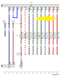
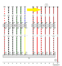
1.png

2.png

Now we can confirm using a multimeter that pin 10 (the big fat red n black one in the photo below) is indeed engine running live!!!!
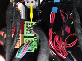
20240321_152418 copy.jpg

Now all that is left for me to do is solder my take-off to charge my EcoFlow Mini!
 
Last edited:
Nice hack!

I've been considering something similar for T6 but to get ignition switched power *from* leisure battery. I was thinking of adding a separate relay that would be fed either from original split-charge feed or from the trailer relay activation (T6 still has a relay for trailer charging) - the feed to trailer socket could remain unharmed for the odd chance of me or somebody else actually plugging in a caravan at some point.

Seems T6 can be tinkered with as well, this is from OBDeleven:

1711038015534.png


EDIT: seems they can be tinkered in T6 but unfortunately results are not great: Ignition Live Under Passenger Seat - How Its Done -
 
Last edited:
This is something I've been investigating too, just not going to tamper until the end of the factory warranty this summer.

I would be cautious pulling a sustained 30amp given discussions elsewhere about cable sizing. You're in a better place underseat than back at the tow socket which was the concern from my 12v EHU approach but even so I'd suggest running at about 20amp if using DC-DC.

Trailers are an infrequent load this would be in use all the time if used for charging. I think also that while the T6 trailer module has an explicit relay for switching this line the T6.1 is done in the module possibly in silicon as I can't hear a relay on mine, so minimising heat would be a good idea.
 
Trailers are an infrequent load
I agree with this generally for lights etc. but pin 10 is an ignition/engine running live specifically for charging 'leisure' batteries in caravans and/or powering fridges when not on EHU and on the move. So in that case wouldn't that be pulling a constant load? Hence it's 2.5mm2 cable and fused at 30amps?

Don't know for certain, but that's what my assumption would be.

Glad to be corrected!
 
It is little bit weird. Look into any recommended amp chart such as the one below, consider the wire lengths to reach the caravan and you'll see 10-15A would be the recommended max current flow and effectively that would translate to max 8-10A charger on caravan. I think they have used 30A fuse in order to withstand pretty heavy voltage drops for a short while. Even so, using only 2.5mm wire with such a fuse on an expected long wire run feels reckless from VW.


1711098838932.png
 
Very interesting @n10n thanks for that - useful chart that. As you say, a bit close to the limits that!!
 
Just by way of follow up to this, what type of cable connectors are recommended for 'splicing' into a cable?


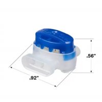
I have some of these triple gel-filled types
411x411-314 1.jpg


Also, some of these 'splicing' thingies

s-l1600.png


I have crimp connectors like these:-

94616_P.jpg

I also have a soldering iron and heatshrink!

What should I be using?!
 
I wouldn't use those splicing thingies nor the crimp connector.
  • take the connector out of the socket
  • depin the pin from the connector if possible (terminal tool kit like https://www.amazon.de/-/en/Release-terminal-removal-connector-extractor/dp/B083B63XR9 is handy)
  • carefully peel about 1cm strip of the wire without cutting the copper (stanley knife and shallow angle) - the peeled section should be couple of cm from the pin, you don't want to solder right at where wire connects the pin
  • peel about 2cm of the wire you will splice in and wrap it tightly around the peeled section so that the result is as thin an even as possible
  • solder the wires together with a small amount of solder
  • cover with heatshrink (if you were able to depin) or self-amalgamating tape if not

I try to not cut the original copper if possible. But it's not always practical - in a tight spot or when doing a splice in a middle of a long run and have to use heatshrink. Then I'll cut but still not use any connector things.
 
Very much what @n10n suggests, the only additional thing I will try if I do this is to find a matching set of connectors.

I have no need of the feed to the trailer so what I'd do is depin the factory connector and make up the loom I want to add in the matching opposite gender connector. Then I can connect them and secure them with a couple of layers of good heatshrink and physically support them with PVC or Tessa tape. Alternatively I could depin the trailer side of the loom connector, make that safe, and put my loom with the equivalent connector in.

That way I have no splices or soldering and I can return the wiring to factory if/when things change.

You could also do the same if you want to keep the trailer feed connected and make up an interceptor Y cable, but I wouldn't recommend that as you may easily end up pulling too much if you have your leisure battery charger and one in a trailer connected at the same time.
 
Edited initial post to move my yellow arrow over to the correct cable in J345 (doh...)
 
Back
Top