[Guide] Solar Cables? . . . - How I Did It -
its time for another guide . . . This time on solar cables.
we use these cables for permanent install and for mobile installs.
lets start with the Solar PV MC4-MC4 cable.
Solar PV cable is not actually standard cable . . . its more specialised.
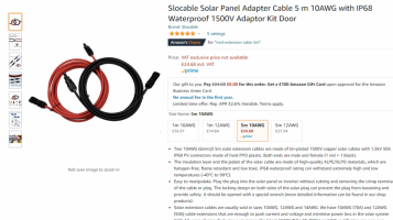
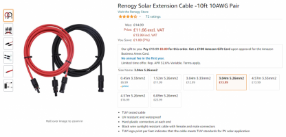
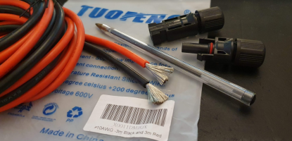
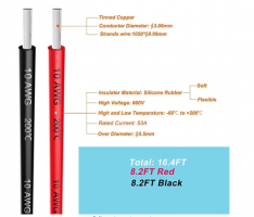
take a look at this cable i got to make up some extension leads:
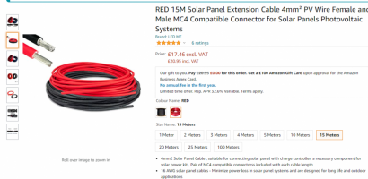
you can see in the spec it states:
This cable has a very wide temp range, from the hottest summer days to the coldest winter deep freezes.
it also has to be UV resistant to stop the sun degrading the sheathing.
The sheathing is made up of two parts, an inner and outer.
the centre metal core is also Tinned copper to help resist corrosion.
The cable comes in various sizes, this example is a 4mm2 / 16 AWG.
+++++++++++++
This is the new cable, 15m of red and 15m of black.
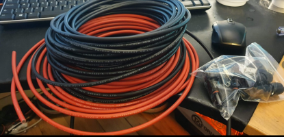
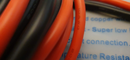
you can see the specs printed on the cable for the EN & TUV standards . .
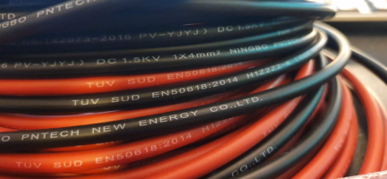
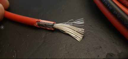
stripping the cable back you can see the construction. The RED outer jacket and the Black inner keep the Tinned coper centre away from the elements.
making the MC4 cables is a simple process provided you have a few basic tools.
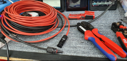
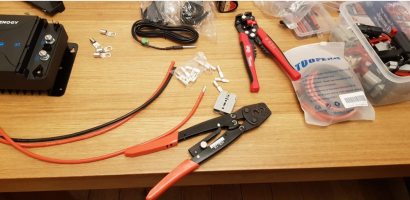
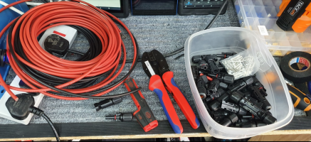
lets take a look at the bench. Here we have the cable, a set of MC4 connectors, a cable stripping tool and a MC4 crimp tool.
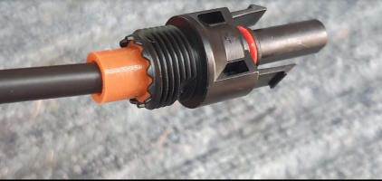
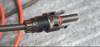
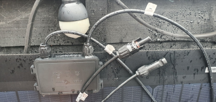
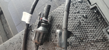
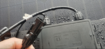
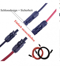
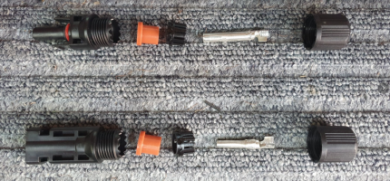
the MC4 connectors are designed like this . . . again they are specially designed to be waterproof, sun proof, weather proof, windproof and need to interlock with each other, requiring a special tool to be opened.
as you can see they come in male and female locking pairs. . . .
which way round they go depends on the install and where the plug is to be fitted . . . . there is a standard convention that follows the flow of power from the panels down to the controller. (more of that later)
lets look at making and end off. . . well start with the red colour cable and a female end.
you will see that the centre crimp pins come in two types, one for the male and one for the female. . . step1 is crimping on the pin so you need to know which pin is for what.
to make it easy for myself i always remember they are opposites . . .
ie
the FAMALE MC4 connector takes the PIN style centre.
the MALE MC4 connector take the HOLE style centre.
so to make a female MC4 end we need the PIN style centre crimp.
++++
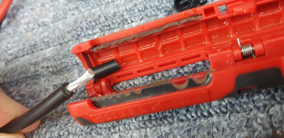
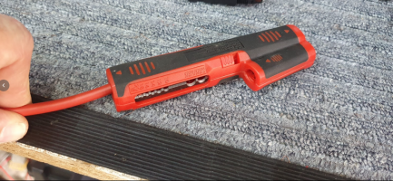
First up is to strip about 15-20mm of the outer sheathing. i like this handy stripper as it cuts through the hard shell and leaves a nice clean end. its actually a coax cable stripper but works very well (I've this one for donkeys years).
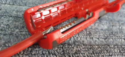
this is a similar version . . . deleyCON Stripper For Coaxial Cable Universal for all: Amazon.co.uk: Electronics

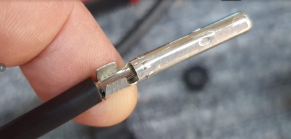
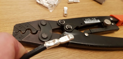
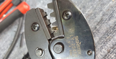
Next up is setting the pin. you can see the cable center goes inside the pin and the tabs will be folded down with the crimper butted up against the sheathing.
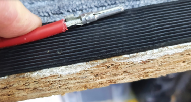
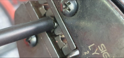
the centre pin site in the MC4 crimpers like this. . . .
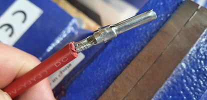
once crimped it should look like this . . . .
++++
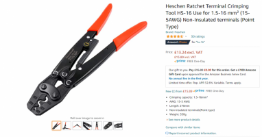
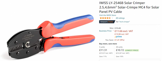
standard crimpers :
++++
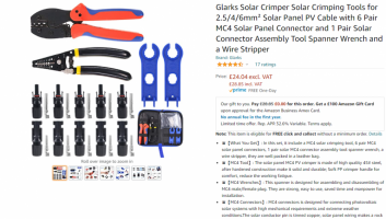
and the starter kit:
++++
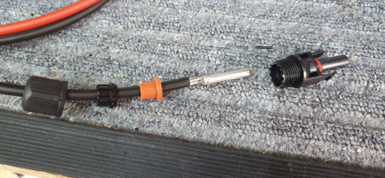
next get the rest of the connector and assemble on the cable like this . .
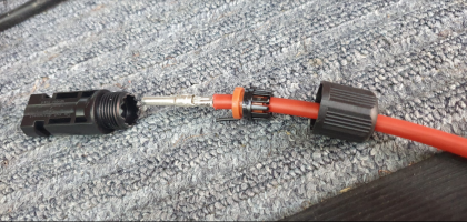
the crimped pin now need to be pushed down inside the MC4 connector until it clicks into place, there are small tabs that lock it down there so it cant pull back out.
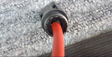
The rubber bung goes down next . . .
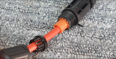
then the finger ring . . .
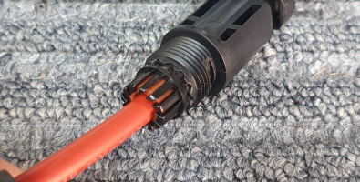
then the end cap screws on to lock it all together . . . . leaving you with a waterproof, connection.
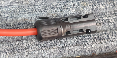
.
its time for another guide . . . This time on solar cables.
we use these cables for permanent install and for mobile installs.
lets start with the Solar PV MC4-MC4 cable.
Solar PV cable is not actually standard cable . . . its more specialised.
take a look at this cable i got to make up some extension leads:
RED 15M Solar Panel Extension Cable 4mm² PV Wire Female and Male MC4 Compatible Connector for Solar Panels Photovoltaic Systems : Amazon.co.uk: DIY & Tools
RED 15M Solar Panel Extension Cable 4mm² PV Wire Female and Male MC4 Compatible Connector for Solar Panels Photovoltaic Systems : Amazon.co.uk: DIY & Tools
amzn.to

you can see in the spec it states:
- Ammonia resistance,UV and ozone resistant,pollution and halogen-free ,
- Good fire-resistant performance, protect against short circuits and ground leakages ;
- Inner Conductor: Flexible Tinned Copper Wire ;
- Dielectric: LSZH Halogen Free Copolymer ; LSZH Halogen Free Copolymer (UV Resistant) ;
- Colour: RED;
- Storage/Operating Temperature: -40°C to +90°C ;
- Minimum Installation Temperature: -5°C
This cable has a very wide temp range, from the hottest summer days to the coldest winter deep freezes.
it also has to be UV resistant to stop the sun degrading the sheathing.
The sheathing is made up of two parts, an inner and outer.
the centre metal core is also Tinned copper to help resist corrosion.
The cable comes in various sizes, this example is a 4mm2 / 16 AWG.
+++++++++++++
This is the new cable, 15m of red and 15m of black.

you can see the specs printed on the cable for the EN & TUV standards . .

stripping the cable back you can see the construction. The RED outer jacket and the Black inner keep the Tinned coper centre away from the elements.

making the MC4 cables is a simple process provided you have a few basic tools.
lets take a look at the bench. Here we have the cable, a set of MC4 connectors, a cable stripping tool and a MC4 crimp tool.

the MC4 connectors are designed like this . . . again they are specially designed to be waterproof, sun proof, weather proof, windproof and need to interlock with each other, requiring a special tool to be opened.
as you can see they come in male and female locking pairs. . . .
which way round they go depends on the install and where the plug is to be fitted . . . . there is a standard convention that follows the flow of power from the panels down to the controller. (more of that later)

lets look at making and end off. . . well start with the red colour cable and a female end.
you will see that the centre crimp pins come in two types, one for the male and one for the female. . . step1 is crimping on the pin so you need to know which pin is for what.
to make it easy for myself i always remember they are opposites . . .
ie
the FAMALE MC4 connector takes the PIN style centre.
the MALE MC4 connector take the HOLE style centre.
so to make a female MC4 end we need the PIN style centre crimp.
++++
First up is to strip about 15-20mm of the outer sheathing. i like this handy stripper as it cuts through the hard shell and leaves a nice clean end. its actually a coax cable stripper but works very well (I've this one for donkeys years).


this is a similar version . . . deleyCON Stripper For Coaxial Cable Universal for all: Amazon.co.uk: Electronics

Next up is setting the pin. you can see the cable center goes inside the pin and the tabs will be folded down with the crimper butted up against the sheathing.

the centre pin site in the MC4 crimpers like this. . . .

once crimped it should look like this . . . .

++++
standard crimpers :

++++
and the starter kit:
Glarks Solar Crimper Solar Crimping Tools for 2.5/4/6mm² Solar Panel PV Cable with 6 Pair MC4 Solar Panel Connector and 1 Pair Solar Connector Assembly Tool Spanner Wrench and a Wire Stripper : Amazon.co.uk: DIY & Tools
Glarks Solar Crimper Solar Crimping Tools for 2.5/4/6mm² Solar Panel PV Cable with 6 Pair MC4 Solar Panel Connector and 1 Pair Solar Connector Assembly Tool Spanner Wrench and a Wire Stripper : Amazon.co.uk: DIY & Tools
amzn.to

++++
next get the rest of the connector and assemble on the cable like this . .

the crimped pin now need to be pushed down inside the MC4 connector until it clicks into place, there are small tabs that lock it down there so it cant pull back out.

The rubber bung goes down next . . .

then the finger ring . . .

then the end cap screws on to lock it all together . . . . leaving you with a waterproof, connection.

.

