I have a general build thread in the works (Our T6 build journey...complete beginners!) but starting a separate thread for the electrics so that people can tell me in one place if i'm going to set my van on fire.
After much research and deliberation we decided to go the lithium route with our build, you can read why here: Lithium Lifepo4 12v Batteries - - - Time For An Upgrade ? - - -.
Thanks to the heads up by @Dellmassive we got a good deal on a Renogy battery (12V 100Ah Smart Lithium Iron Phosphate Battery) £639 and also went for the Renogy DCC50S for the reasons outlined in the same thread (re: low temp protection all in one box).
So onto the install, never done anything like this before and hadn't been near electrics (aside of a car stereo) since science at school so had a lot to learn and still do!
Useful reading for anyone attempting are the various 'How i done it' threads from Dell, you can find them all here: Dellmassive`s -- "how I Done It" -- Thread
In addition I followed Martyn's (@travelvolts ) guide on how to get from cab to starter battery with a heavy gauge cable etc. https://docs.wixstatic.com/ugd/d959f6_3ed319f968954720a73c38807b437278.pdf
Aside of the battery and charger I forked out on a bit of kit as I imagine i'll be needing it in the future anyway...here's the list:
- USB Charger Voltage Meter - https://www.amazon.co.uk/gp/product/B07XR82PCW/ref=ppx_yo_dt_b_asin_title_o01_s00?ie=UTF8&psc=1
- Lug Crimp Terminals - KANOSON 60pcs Crimp Connectors,Bolt Hole Tinned Copper Terminals Set with Storage Box- Electrical Connectors Crimp Terminals Cable Lugs Battery SC Wire Ring Connectors for Marine, Automotive,Electric: Amazon.co.uk: DIY & Tools
- Wire Cutters/crimps/strippers - Wire Stripper, DANIU Stripper Cutter AWG10-24 Compound Automatic Wire Stripper Plier 3-in-1 Hand Tool Self-Adjusting Cable Stripper, Wire Cutter and T
- Heat shrink tube - Yakamoz 150pcs 2:1 Polyolefin H-Type Heat Shrink Tubing Tube 8 Sizes Sleeving Wire Cable Kit with Case – Black/Red: Amazon.co.uk: DIY & Tools
- Cable crimping tool (one of the few places that had it in stock) - Draper Battery Terminal Crimping Tool
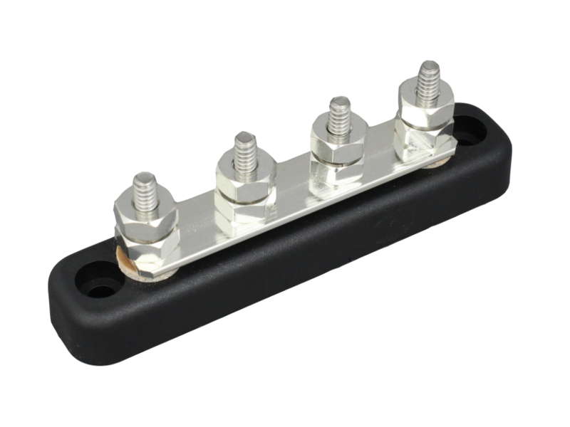
- 12 way earth block - 8-Way Earth Block
- Wiring kit from @travelvolts - DC-DC charger Wiring kit XL. | travelvolts
- 12 gang fuse Box - 12 way fuse box with negative rail. | travelvolts
It's not the exhaustive list of everything you'll need (i already had a heat gun, multimeter and various other tools)
So first off was to get the thick red cable from the wiring kit through from the cab to the engine bay, I followed the @travelvolts CTEK installation guide for this which was invaluable in terms of located the correct grommet etc.
It's fair to say this was a pain in the ass, the guide assumes you have a rubber matting floor which i think might have been easier but with carpet, not so much.... You remove the end panel of the dash, glove box and fuse box cover (all covered in the guide) and then look up in the corner under the sound deadening and there's the grommet. It was a bit trickier to get at for me as i have drains that run out in exactly that spot for the Hilo roof (fitted by Viper Tech in Salford Quays along with the windows) but got there in the end. I also had to take both passenger and drivers seat out to get enough carpet up to work with.


Pushed the cable through, connected up to the fused part of cable that comes in the Travelvolts cable kit and then just left it there for the time being.
Back into the van it was time to run the cable from the passenger footwell to the drivers seat, again followed the guide but with carpet this was pretty hard work without taking the carpet out completely. Getting the cable through the black cable tunnel and out the hole on the far was fiddly, i ended up having to pull up the cable tunnel on the near side and push it across. With a bit of perseverance got there in the end, also ran an ignition live cable (from the fuse box) at the same time (from the Travelvolts kit) and tie-wrapped both cables to the existing cable runs.
The wiring kit comes with a piggy bag adapter to easily connect the IGN live to the front of the fuse box and avoid taking the whole thing out.


After connecting the IGN cable to the fuse box I used the multimeter to check the slot was indeed dead until the IGN was on, all good.
Battery, battery charger, fuse box and ignition live feed all need a ground point so had to work out the best way to do that... after some digging i spotted a ground point under the driver seat where the cables are routed under the carpet.

So using an earth block, some spare cable from the wiring kit, the crimp lugs, heat shrink etc. i made a cable and brought a more accessible ground feed out to under the seat. This is the bit i wasn't sure is good practice (@Dellmassive legit solution?)


Next up i had to find a way to secure the battery and battery charger. Using some of the holes in the seat base, a piece of timber and some simple L brackets, I fashioned a brace/support bar.


Just happened to be the perfect distance form the front of the seat to hang the Renogy box and be able to see the display under the front of the seat.

Next was a case of running all the relevant wires from Renogy box to battery etc. IGN live from fusebox to Renogy box. The Renogy box comes with a 2 core IGN feed cable which is tricky to deal with as there was no obvious common ground at the fuse box end so instead, I used the single IGN live cable that came with the TravelVolts kit to run the +ve and then a spare bit of cable to run a -ve feed to the earth block.
I added some padding (leftover dodo thermo liner) to the wood baton and the battery fits up against it very snugly


I also added a thin piece of ply to the back to seal up the hole under the seat, give the battery something to brace against on the other side and give me somewhere to attach the fuse box (with sticky foam pads for now). I only have lights in there for now so fuse box feels OK there but i imagine when i add more appliances and some furniture i may well relocate the fuse box out of there into somewhere more accessible.
When i had the Hilo roof fitted we had some spots fitted in the roof and the cables were run down to the drivers seat, so I added some crimps to the cables (from the Travelvolts 12 gang fuse box kit, it comes with a selection of crimps and fuses) and wired them into the fuse box with 5amp fuses.

So I have the -ve from the battery, the charger, the IGN live feed and the fuse box all going to the common ground earth block I created (@Dellmassive good practice or not??)
The battery doesn't move anywhere but i do need to create some more braces on the right side to stop any possible left/right movement.
I screwed the earth block to a piece of timber and attempted to use that as a brace for the battery but not entirely happy with it and don't know whether it's a good idea to have that earth block sat amongst all the cables or not??

The leisure battery comes in shelf mode and needs to be 'switched on' using the blue RJ45 cable. So at this point with everything wired up, i went back to the engine bay and connected the red cable to the +ve on the leisure battery.
The Renogy box lit up and at this point i changed the battery type using a pin to the Lithium profile (blue light). I noticed the service battery indicator LED was slow flashing red (battery over discharged) and it occurred to me that it must think the battery is flat as it was still in shelf mode. Soon as I switched the battery on the light turned yellow (battery voltage normal).
Now was the moment of truth, what happens when I start the van... at first nothing, then after a couple of seconds, the Alternator Charging LED turned red to indicate the alternator was charging the battery, happy days!

When he ran the cables for the lights, Stewart (Viper Tech) also fitted a nice little switch in the door pillar...

and we have light!

(the 2 at the back are on a separate circuit and are touch on/off night lights - also worked!)
I plugged the battery monitor into the 12v socket on the dash and got a reading of 11.7v... should be much higher right?

@Dellmassive - I haven't driven the van properly for months due to lockdown and also had to jump it 2 weeks ago so i imagine it needs a good run out to charge but also wondered whether this low reading could be due to those fuses that are still connected to the starter battery -Ve giving a false reading... I still need to relocate those somewhere...
The other big omission, I don't have any battery monitoring yet for the leisure battery, as I can't really go anywhere anyway, i was planning on hanging on until the Renogy display becomes available in the UK in August... I'm assuming there's little point in me putting on a BM2 monitor on the Lithium battery and likewise, don't really want to lay out £200 for the Victron monitor when i can hopefully get the Renogy one in time for £50...should give me what i need?
Do you see any problems with how I've wired it, am I likely to burn it down and void my insurance!?
After much research and deliberation we decided to go the lithium route with our build, you can read why here: Lithium Lifepo4 12v Batteries - - - Time For An Upgrade ? - - -.
Thanks to the heads up by @Dellmassive we got a good deal on a Renogy battery (12V 100Ah Smart Lithium Iron Phosphate Battery) £639 and also went for the Renogy DCC50S for the reasons outlined in the same thread (re: low temp protection all in one box).
So onto the install, never done anything like this before and hadn't been near electrics (aside of a car stereo) since science at school so had a lot to learn and still do!
Useful reading for anyone attempting are the various 'How i done it' threads from Dell, you can find them all here: Dellmassive`s -- "how I Done It" -- Thread
In addition I followed Martyn's (@travelvolts ) guide on how to get from cab to starter battery with a heavy gauge cable etc. https://docs.wixstatic.com/ugd/d959f6_3ed319f968954720a73c38807b437278.pdf
Aside of the battery and charger I forked out on a bit of kit as I imagine i'll be needing it in the future anyway...here's the list:
- USB Charger Voltage Meter - https://www.amazon.co.uk/gp/product/B07XR82PCW/ref=ppx_yo_dt_b_asin_title_o01_s00?ie=UTF8&psc=1
- Lug Crimp Terminals - KANOSON 60pcs Crimp Connectors,Bolt Hole Tinned Copper Terminals Set with Storage Box- Electrical Connectors Crimp Terminals Cable Lugs Battery SC Wire Ring Connectors for Marine, Automotive,Electric: Amazon.co.uk: DIY & Tools
- Wire Cutters/crimps/strippers - Wire Stripper, DANIU Stripper Cutter AWG10-24 Compound Automatic Wire Stripper Plier 3-in-1 Hand Tool Self-Adjusting Cable Stripper, Wire Cutter and T
- Heat shrink tube - Yakamoz 150pcs 2:1 Polyolefin H-Type Heat Shrink Tubing Tube 8 Sizes Sleeving Wire Cable Kit with Case – Black/Red: Amazon.co.uk: DIY & Tools
- Cable crimping tool (one of the few places that had it in stock) - Draper Battery Terminal Crimping Tool
- 12 way earth block - 8-Way Earth Block
- Wiring kit from @travelvolts - DC-DC charger Wiring kit XL. | travelvolts
- 12 gang fuse Box - 12 way fuse box with negative rail. | travelvolts
It's not the exhaustive list of everything you'll need (i already had a heat gun, multimeter and various other tools)
So first off was to get the thick red cable from the wiring kit through from the cab to the engine bay, I followed the @travelvolts CTEK installation guide for this which was invaluable in terms of located the correct grommet etc.
It's fair to say this was a pain in the ass, the guide assumes you have a rubber matting floor which i think might have been easier but with carpet, not so much.... You remove the end panel of the dash, glove box and fuse box cover (all covered in the guide) and then look up in the corner under the sound deadening and there's the grommet. It was a bit trickier to get at for me as i have drains that run out in exactly that spot for the Hilo roof (fitted by Viper Tech in Salford Quays along with the windows) but got there in the end. I also had to take both passenger and drivers seat out to get enough carpet up to work with.
Pushed the cable through, connected up to the fused part of cable that comes in the Travelvolts cable kit and then just left it there for the time being.
Back into the van it was time to run the cable from the passenger footwell to the drivers seat, again followed the guide but with carpet this was pretty hard work without taking the carpet out completely. Getting the cable through the black cable tunnel and out the hole on the far was fiddly, i ended up having to pull up the cable tunnel on the near side and push it across. With a bit of perseverance got there in the end, also ran an ignition live cable (from the fuse box) at the same time (from the Travelvolts kit) and tie-wrapped both cables to the existing cable runs.
The wiring kit comes with a piggy bag adapter to easily connect the IGN live to the front of the fuse box and avoid taking the whole thing out.
After connecting the IGN cable to the fuse box I used the multimeter to check the slot was indeed dead until the IGN was on, all good.
Battery, battery charger, fuse box and ignition live feed all need a ground point so had to work out the best way to do that... after some digging i spotted a ground point under the driver seat where the cables are routed under the carpet.
So using an earth block, some spare cable from the wiring kit, the crimp lugs, heat shrink etc. i made a cable and brought a more accessible ground feed out to under the seat. This is the bit i wasn't sure is good practice (@Dellmassive legit solution?)
Next up i had to find a way to secure the battery and battery charger. Using some of the holes in the seat base, a piece of timber and some simple L brackets, I fashioned a brace/support bar.
Just happened to be the perfect distance form the front of the seat to hang the Renogy box and be able to see the display under the front of the seat.
Next was a case of running all the relevant wires from Renogy box to battery etc. IGN live from fusebox to Renogy box. The Renogy box comes with a 2 core IGN feed cable which is tricky to deal with as there was no obvious common ground at the fuse box end so instead, I used the single IGN live cable that came with the TravelVolts kit to run the +ve and then a spare bit of cable to run a -ve feed to the earth block.
I added some padding (leftover dodo thermo liner) to the wood baton and the battery fits up against it very snugly
I also added a thin piece of ply to the back to seal up the hole under the seat, give the battery something to brace against on the other side and give me somewhere to attach the fuse box (with sticky foam pads for now). I only have lights in there for now so fuse box feels OK there but i imagine when i add more appliances and some furniture i may well relocate the fuse box out of there into somewhere more accessible.
When i had the Hilo roof fitted we had some spots fitted in the roof and the cables were run down to the drivers seat, so I added some crimps to the cables (from the Travelvolts 12 gang fuse box kit, it comes with a selection of crimps and fuses) and wired them into the fuse box with 5amp fuses.
So I have the -ve from the battery, the charger, the IGN live feed and the fuse box all going to the common ground earth block I created (@Dellmassive good practice or not??)
The battery doesn't move anywhere but i do need to create some more braces on the right side to stop any possible left/right movement.
I screwed the earth block to a piece of timber and attempted to use that as a brace for the battery but not entirely happy with it and don't know whether it's a good idea to have that earth block sat amongst all the cables or not??
The leisure battery comes in shelf mode and needs to be 'switched on' using the blue RJ45 cable. So at this point with everything wired up, i went back to the engine bay and connected the red cable to the +ve on the leisure battery.
The Renogy box lit up and at this point i changed the battery type using a pin to the Lithium profile (blue light). I noticed the service battery indicator LED was slow flashing red (battery over discharged) and it occurred to me that it must think the battery is flat as it was still in shelf mode. Soon as I switched the battery on the light turned yellow (battery voltage normal).
Now was the moment of truth, what happens when I start the van... at first nothing, then after a couple of seconds, the Alternator Charging LED turned red to indicate the alternator was charging the battery, happy days!
When he ran the cables for the lights, Stewart (Viper Tech) also fitted a nice little switch in the door pillar...
and we have light!
(the 2 at the back are on a separate circuit and are touch on/off night lights - also worked!)
I plugged the battery monitor into the 12v socket on the dash and got a reading of 11.7v... should be much higher right?
@Dellmassive - I haven't driven the van properly for months due to lockdown and also had to jump it 2 weeks ago so i imagine it needs a good run out to charge but also wondered whether this low reading could be due to those fuses that are still connected to the starter battery -Ve giving a false reading... I still need to relocate those somewhere...
The other big omission, I don't have any battery monitoring yet for the leisure battery, as I can't really go anywhere anyway, i was planning on hanging on until the Renogy display becomes available in the UK in August... I'm assuming there's little point in me putting on a BM2 monitor on the Lithium battery and likewise, don't really want to lay out £200 for the Victron monitor when i can hopefully get the Renogy one in time for £50...should give me what i need?
Do you see any problems with how I've wired it, am I likely to burn it down and void my insurance!?
Last edited:


")
