Fitting Eberspacher D2 - My Experience

I have quoted the section in the manual as to the purpose of the white/red wire. Page 26

Link for manual a couple of pages back - looks like some of your other wires are for can-bus, see manual

Thanks @oldiebut goodie.. so it‘s for use with the Ebers diagnostic kit for configuring the heater ?
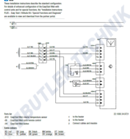
If understand correctly, the Easystart Pro only requires the 4 way connector connecting. The remaining 5 unterminated wires are not required?
 
Presumably your kit should be connected to Can-bus as it is a can-bus specific kit but I can't help as I don't have any more info other than the manual. I work on air Webastos only but it looks as though you should have some further wiring diagrams with your kit to tie in with the manual.
 
Hi wills, your first message about the wiring of the easystart pro is well said, the 4 way connector is pre made in the harness and the colours match perfectly, but the rest of the wire colours in the harness don’t match the remaining 3 pin connector on the back of the easystart controller.
I hope you get an answer as wiring the controller is my last job on the heater instal, I’m waiting for a friend to lend me his crimper, but lock down has put that on hold for me.


Is it me or are the D2L installation instructions a bit thin, contradictory and confusing?
I’m currently fitting the wiring and need help.
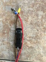
The Easystart Pro wiring diagram and the Ebers supplied harness don’t match. The XS1 4 wire block connector is premade and matches the diagram. The XS2 3 wire connector needs making up. The diagram shows 1 - BN/WH, 2 - GY/BK & 3 - GY. The controller pre made connector is correct but the harness has a 5 wire option of BN/WH, YE, RD, GY/RD & BU/WH.Any help appreciated.

View attachment 71577
 
Maybe they expect the installation not to be carried out by DIY’ers...
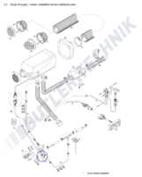
Hi Wills, Maybe this diagram can help, if not it may help you to tell me where the problem is.

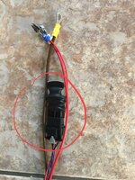
I believe the plug your photo showed earlier is in the red circle (22).
If so you can see from this the lead that splits off (labelled 6) with 4 wires goes to the controller (23)
The other lead that comes from the split is not numbered but goes to the blue circle and connects to the fuel pump. SO therefore there should be 2 wires in that lead.

Does this make sense or have I got the wrong bit you cant figure out?

Screenshot 2020-05-27 at 16.49.49.png
 
Hi skyliner33, sorry to jump in and answer for wills, but I think he’s talking about the controller wiring No 23 on your diagram, if you go back a page or 2 in this thread, to the post where he put a picture of the loom laid out on his patio you can see the wires circled controller, and his final paragraph in the patio picture post, states his problem.
 
Thanks @Skyliner33 & @Blizzard , the above diagram confirms my beliefs. The loom maybe an Ebers generic but all the connectors are already made up for the T6. Sort of plug n play.
The 2 way fuel pump connection and 4 way controller connection are already made up and the fuse block pins are colour coded and crimped in position. So no crimping but maybe shrink wrapping the spare wires.
Any idea what 8 is in the diagram?
 
Hi wills, your first message about the wiring of the easystart pro is well said, the 4 way connector is pre made in the harness and the colours match perfectly, but the rest of the wire colours in the harness don’t match the remaining 3 pin connector on the back of the easystart controller.
I hope you get an answer as wiring the controller is my last job on the heater instal, I’m waiting for a friend to lend me his crimper, but lock down has put that on hold for me.

So if you have the same harness as mine then there’s no crimping required just PnP. Maybe shrink wrapping all the spare wires.
 
Thanks @Skyliner33 & @Blizzard , the above diagram confirms my beliefs. The loom maybe an Ebers generic but all the connectors are already made up for the T6. Sort of plug n play.
The 2 way fuel pump connection and 4 way controller connection are already made up and the fuse block pins are colour coded and crimped in position. So no crimping but maybe shrink wrapping the spare wires.
Any idea what 8 is in the diagram?
8 is the air intake pipe for the combustion part, (not the air that gets heated and passes into the van). Its the same material as the exhaust and has a stainless steel end tip.

Thats strange mine was a T6 specific kit and I had to make up one connector.
 
Maybe it’s marked as B then, adjacent to the fuse holder. This in the pic. Mmmmm... make note, I need to clean the floor.

image.jpg
 
Maybe it’s marked as B then, adjacent to the fuse holder. This in the pic. Mmmmm... make note, I need to clean the floor.

View attachment 71768
Ok, in that pic the brown with yellow ring loop is the negative to the battery. The two reds with the pins at the end go into the Eberpacher fuse box. There are space for 3 fuses, only 2 are used. This is in the photo I posted yesterday.
 
Don’t be bugged as there was no bracket in my kit either.. So what is it?
 
So we don’t know what it is? Where did you source the diagram from please?
 
Back
Top