Definitely Orange and Green then? Haha

Doing this tomorrow.
Definitely Orange and Green then? Haha

Doing this tomorrow.
yea if you want to do the naff connection at the light unit with no body connection to dissipate the heat, they get HOT.
The info I posted was ONLY for connecting under the seat.
 
yea if you want to do the naff connection at the light unit with no body connection to dissipate the heat, they get HOT.
The info I posted was ONLY for connecting under the seat.
Ideally id rather do it under the seat. I just need to know exactly which ones to go into under the seat. I don't have a wiring diagram and aren't too familiar. Just need to know which ones so I can replicate it.
 
They were only used to test the circuit, I would advise not using them as they are rubbish, get hot as they can have high contact resistance and usually sever a few strands of wire. I cut the wire and used proper terminals in the housing once I was happy with the circuit.
But they came with the resistors.
 
Where did you get your scotch lock adaptors from? I had some from Halfords but they didn't work as the wires on the lights are so thin.
They are BT (openreach) gel filled ones, speak nicely to the next engineer you see sat in a manhole.
 
I can supply cable/plugs for this, send me a pm
Hi Pauly can you sent me the info please as i would like to swap my none led t6 rears to led 6.1 rears genuine ones the ones i seen say the come with a block and the pins/wires need repositioning any help would be great

kevin.
 
EC9FE6DB-D16C-48CA-92E7-71B46333C13B.png
The purple lock needs to be slid to first detent (not removed) to allow tool to be inserted to free the terminals.
You need to add a repair wire to each connector and link in headlining loom to have two reverse and two fog. You also need to fit two suitable resistors. Only one side connector shown, you can work the other side out from the CFD Robert posted.

29471BC3-FE3D-45A8-A210-DBC47FBDF0EA.png

99766605-54CC-4BC2-A62D-2B21B020F476.png
 
  • Like
Reactions: mmi
View attachment 134101
The purple lock needs to be slid to first detent (not removed) to allow tool to be inserted to free the terminals.
You need to add a repair wire to each connector and link in headlining loom to have two reverse and two fog. You also need to fit two suitable resistors. Only one side connector shown, you can work the other side out from the CFD Robert posted.

View attachment 134102

View attachment 134103

Absolutely brilliant thank you very much the only thing now is which wire do i break into to put the resistor and i don’t suppose you know the spec and where i can obtain them from. Sorry for being a pain Kevin.
 
It’s all already in the thread. Can’t spoon feed you too much. Two schools of thought for the position of the resistor. Make sure you use wire seals (as seen in first photo) or you risk filling your expensive lights with water.

13FD6F41-98D3-4C31-8529-1A3085448B30.png


DFB29BB4-EA71-4F72-867C-9AA34BD9AE0D.png

258C8795-D133-4AA9-9FCF-395326834613.jpeg

910ACB60-115A-4582-80C3-142546C33146.png
 
Last edited:
Thank you for all you’re help I try and find the (thread) and read through it new to all this threads etc. But like you say i need to get to grips with it. kevin.
 
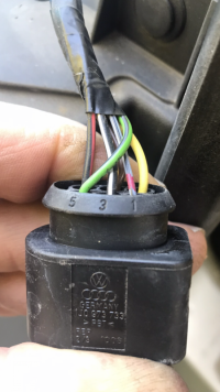
To be clear, a single yellow repair wire (or terminal if you have them) needs to be inserted in each port on the plug (think it’s position 2 from memory for both O/S & N/S) to get the additional fog one side and reverse the other to work. These wires need a wire seal fitted. The wires de pinned from the original plug already have seals on them. Different colours denote different wire diameters and it matters you get the correct seal or it will let water in.
 
Does anyone know where i can get a pair rear LED light connecting blocks for t6.1 i want to convert my t6 to aftermarket 6.1 lights with 2 reverse lights, fog lights and sequential indicators as I been told genuine VW only have standard indicators. Thanks kevin
 
Use the part number highlighting and order from TPS or your local dealer.
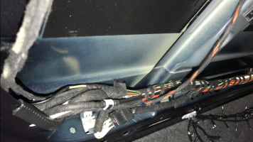
You will need a repair wire which comes with a terminal at each end, cut it in half then you will have a repair wire for each side. Extend this wire (use hermetically sealed ferrule) and run the wires to the left rear roof area to access the wires to connect into.
So 2x 1J0 973 733 Terminal Housing
1x Repair Wire 000 979 133 E (1.0mm) cut in half and fit blue seal. Insert into pin 2 on each terminal housing. Lock the purple clip into place once all the wires have been inserted or it won’t fit the light connector.
2x wire seals 06A 972 741 D (blue)
2x repair ferrules 000 979 941 (red NB heat the sleeve with hot air gun to shrink, make sure even heat to seal correctly, glue should come out of each end slightly, but don’t overheat. Using a lighter is just gash).

Or I could price it all up for you tomorrow and make them for you. I would use a single wire rather than having the join, you would just need to de pin the wires from your van and insert into the housing.


E8237699-8F39-4C1F-8E66-DEAA21A100D4.jpeg

You are going for the factory look, remove all the original loom tape to the rubber bung, feed your new yellow repair wire through the grommet (and into the van) then tape it up with the other original wires keeping it the same without bunching with fresh good quality tape. Notice to tape over the rubber grommet to keep the water out. Leave some wires free of tape close to the plug to keep some flexibility.


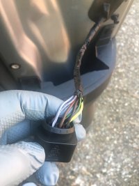
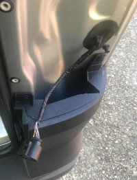
MX4 Pins 1 to 5.jpg

MX4 Pins 2 to 6.jpg

MX4 LED OS PLUG.JPGMX4 With Repair Wire Fitted.jpg
 
Last edited:
hi flyingspanner

that sounds absolutely fantastic thank you so much for offering to do this for me, if it’s ok i would like to take you up on your offer just let me know the cost and i will transfer the moneys to you directly

kevin.
 
hi flyingspanner

that sounds absolutely fantastic thank you so much for offering to do this for me, if it’s ok i would like to take you up on your offer just let me know the cost and i will transfer the moneys to you directly

kevin.
I will get them ordered from TPS tomorrow.
 
ps i’ve also ordered the same resisters that you show in your photos and i agree what a fantastic idea to fit them under the seat from a cooling off point of view just need to work out which wires to break into thanks once again.

kevin.
 
ps i’ve also ordered the same resisters that you show in your photos and i agree what a fantastic idea to fit them under the seat from a cooling off point of view just need to work out which wires to break into thanks once again.

kevin.
I will give you the details when sending the terminal housings. NB there are two wires the same colour in one of the blocks you need to connect into, make sure you take your time and connect to the correct one. You will know if you made a mistake as you will still get the hyper flash on the dash for one side only.
 
I will give you the details when sending the terminal housings. NB there are two wires the same colour in one of the blocks you need to connect into, make sure you take your time and connect to the correct one. You will know if you made a mistake as you will still get the hyper flash on the dash for one side only.
brilliant thank you much excited all ready he he

kevin.
 
Back
Top