Seeking Feedback on Electrical Diagram for my project

ArtD

Member
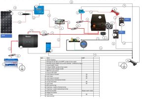
Hey folks, I know this might cover some familiar ground, but I'm reaching out to tap into the collective wisdom of this community. I've put together the electrical diagram for my project, and I'd be truly grateful for your critical views and insights.

Relevant Details:
  • Leisure Battery: Tucked neatly under the driver's seat.
  • AC: No plans for AC at the moment, but might consider it down the road (time will show)
  • Charging Options: Looking to charge the leisure battery from the alternator, or solar panels (PV)/ mains power with the flexibility of on-demand charging when available or parked (so could be plug-in on demand for PV or mains).
Key Points for Your Feedback:
  1. Connections: Are the connections for the leisure battery, solar panels, alternator and mains charger correctly depicted in the diagram or have I missed some?
  2. Fuse Sizes: Do the proposed fuse sizes for each connection point seem appropriate?
I recognize these questions might echo what's been discussed before, but I'm eager to get a fresh perspective. and I want to ensure that I'm not overlooking or overspec, hance any potential improvements or safety considerations, would be welcomed

Feel free to dive into the details, share your experiences, or suggest any modifications you think would enhance the setup or simplify it.

Thanks a bunch for taking the time to lend your expertise!Draft Project.jpg
A - 35mm, B - 6mm
 
Couple of quick thoughts

You've no master fuse on that lithium battery, you seem to be trying to use of the £20 multiway fuse blocks for several things (13) instead and really if you are protecting your van from a runaway short on 230Ah lithium you want something built for the purpose and much much closer to the battery.

You seem to be trying to use cutoff switches and circuit breakers and fuses - that's a lot of high current connections to either fail or add resistance and heat. Stick to just fusing and, if you need to, a cut-off switch that is rated to break likely fault currents.
 
Welcome.

My thoughts are overkill - may be nonsense and happy to be educated, but….

1. Not sure why you would need a fuse at both ends of the main vehicle battery > Renogy wire? (21 & 22) seems overkill. I would put one as close to the vehicle battery as possible.
2. The main output feed from the Renogy should go straight to the positive of the house battery - you’ve got a load of breaks in that wire that will generate heat/resistance. You should use a midi fuse in that line too.
3. I would use inline MC4 fuses from the solar panel to the MPPT instead of the breaker (4)
4. The output positive from the house battery needs to be fused again as close as possible to the battery and then I would run to a busbar to feed all the various circuit/devices/sub fuse boxes.
5. If you have a smart alternator you need an ignition live/charge feed to the Renogy to wake it up.

Trying to make the vehicle>renogy>house battery path as clean as possible.

Also you’ve stated 35mm2 cable which is upto 240A rated, is this overkill too as the Renogy will only be pushing 50A max and I can’t see an invertor or anything else that will pull a huge load?
 
You have a separate MPPT. You could use the one built into the Renogy unit provided you choose a solar panel with a suitable maximum voltage, and then it would also top up your vehicle battery once leisure battery is full. That would be why you would have a fuse at each end of the Renogy- vehicle battery link.
 
Other reasons that the main feed from starter to your leisure electrics is commonly fused both ends is that you want it fused as close to the source as possible so the whole cable run is protected. That can make that fuse inaccessible, especially if you use the OE fusebox under the battery.

Having a second slightly lower fuse (I think OE is 100A at starter and 80A by leisure) at the other end means it's in an accessible place. It also gives a handy point of isolation.

Also in older systems with a split charge fusing this way protected you against a stuck charge relay keeping the cable energised.
 
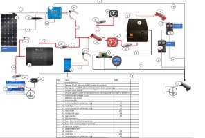
Hi guys, thank you for initial suppport. I had a review based on your comments and put few changes and also need to clarify few:
- no smart alternator so no ignition feed needed
- distribution fuse box ( now no 12 see below) - would act as on demand input from PV or charger as I would use anderson plugs to connect.
- I know about temperature sensor (but not put it on the diagram)

Untitled.jpg
 
21- main switch should be on POS side.

no need for 8 - LBP as Roamer BMS has this feature built in.

and as @roadtripper says . . .

stay away from cheap breaker switches - they just get hot.

add a master main fuse, - that can then feed your POS busbar or MIDI/MAXI fuse block.

add a master main isolator,


Remember the fuse is there to protect the cable, so always "fuse rate" under the "cable rate."


if no Smart ALT - what is this all being fitted in?
 
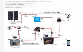
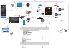
Updated version based on feedback (Dell I have seen your diagram and used it as a base but wanted more details in it, and looking for flexibility to plug in/out charger and PV on demand.
Installation to My10 T5.1 102 T30 SWB

Untitled.jpg

considering in the future inverter (or not if I will go different route e.g. power bank) so want to make it easier to change down the line.
 
Looking better and simpler, I'd just question why you need a second large fuse, isolator and bus bar for your load fuseboxes?

Are they going to be physically separate and you need to protect that cable run? Even then running high capacity cable to the isolator and lower capacity then to the bus bar is a bit odd.

Why do you have an Anderson tapping off the feed to the DC-DC?
larger fuse - distance from front to end of the car (although I migh end up with 60A potentially) - fuseboxes are going to be separated for different loads (I'm still thinking about primary and secondary load option to triger to switch on/off based on battery level)
Anderson to dc-dc feed for PV as and when needed (not planning to have one on roof but only on demand, so could use both victron and renogy at the same time for panels)
 
What use case are you going to need automated load shedding in a van as small as a Transporter with pretty much the largest available lithium battery installed in?

You seem to be adding complexity and connections for future choices you may not make that would compromise your use of the system in between. @Dellmassive tends to use a lot of Andersons and options because leisure electrics are pretty much his hobby it seems - are you planning the same frequency of changes to your system?

With electrical systems by and large the simpler they are the more robust and effective they are.
 
So the likelihood is that I want to give 2 level of priority: first to fridge, diesel heater and 2 lights, second to rest of usbs, plugs lighting, etc. The second would be cut off completely below certain battery level. I know can be done manual but I don't want to spend most of my time waching each app and monitor battery load, so automated option would be ideal. Or perhaps unnecessary 'need' of mine.
Andersons - easy to plug in/out in my situation i.e. on demand plug in/out
 
OK, but if you are happy to manually plug in and out chargers according to your need, why not just turn circuits on and off by hand too?

But again what are you planning to do with this electrical system? Weekend camping, mobile office, preper vehicle?

Why do you think you need to unplug your charging sources?

Why do you need to load shed when you have the largest lithium battery you can get on your plan?

It's really hard to advise with only half the picture - the other half is your loads and usage pattern.
 
Hi Roadtripper, so few things to add:
- weekends camping plus odd full weeks in the year
- load usage approx 242Ah per day (almost half for fridge)
- not close to vehicle every time so don't want to end up surprised with battery drainage (especially when back in the evening)
- charing sources plug in - ok victron charger can be parmanent solution (as I have ctek for other stuff), but PVs on demand (depends on the spot and whether away from vehicle or not)

l considered multiple times to have PVs on roof (attached) but discounted this option.
 
How are you reaching 242Ah per 24 hours - that's an average load of 10A which is very high unless your fridge is absorption or peltier?
 
How are you reaching 242Ah per 24 hours - that's an average load of 10A which is very high unless your fridge is absorption or peltier?
on average 3.84-4.2A per hour - it drops to below 2 but in warm conditions it doesn't so I take the scenario of 4.2A
 
on average 3.84-4.2A per hour - it drops to below 2 but in warm conditions it doesn't so I take the scenario of 4.2A
Your compressor fridge may draw 4a but even in the hottest temps it won’t be on all the time. They are well insulated and the compressor is thermostatically controlled. Even in France last June in 35degrees my compressor was only firing for about 15 minutes per hour during the day and much less at night.
 
this potentially chan
Your compressor fridge may draw 4a but even in the hottest temps it won’t be on all the time. They are well insulated and the compressor is thermostatically controlled. Even in France last June in 35degrees my compressor was only firing for about 15 minutes per hour during the day and much less at night.
This potentially changes the requirements slighly, and means I can add other things instead but would need to check.

Just another element on the diagram - BMV 712 and shunt - is it needed knowing roamer or fogstar have their own BMS system to monitor similar parameters? thx
 
Back
Top