Renogy DCC50S Display

Riker1 - for the renogy connector pinout see post #11.


I had to connect the 0V too, without the comms is unreliable. To keep the renogy cable in one piece, I used one of these;

1612001062789.png

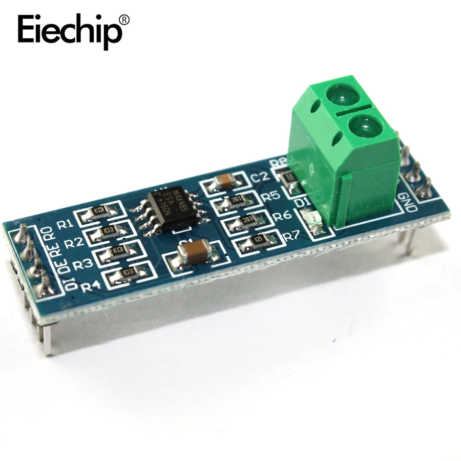
Also worth noting; I tried to use the renogy 5V (pin 1) to power my arduino/OLED, 200mA is easily enough for this BUT, it seems that the MAX485 output burst cripples it. Every 2 second (my poll rate) the 5V dips and the OLED dims. I have read that the 120ohm terminators can be increased, or even omitted in some circumstances, but my quick fix was to power the whole thing from 12V and a buck converter.
 
Hi Jayd,

I am struggling with the pinouts. On the MAX485 n the board:
Code:
  // Definitions
  #define ENC_A     3
 
  #define ENC_B     4
  #define ENC_PB    5
  #define MAX485_DE 2 //Modbus RTU

Code:
DI    Driver-In                TXD
DE    Drive-Enable         d3
RE    Receive enabled    d2
RO    Receive out           RXD

Pinout MAX485

I thought ENC_A - if this is A in - is this referenced to DE?
Could you confirm the mapping and pinout for DI/DE/RE/RO?

Thanks a lot
 
...
I'm using an arduino leonardo (clone) at the moment, but plan to swap to a nano.
Here's mine so far;
Hi JayD, do you have the arduino leonard version which can be send? having an issue with my boards Mega (serial Ports) or Leonard ( code to big)

Thanks a lot T
 
ENC_ is the rotary encoder, nothing to do with comms.

For nano33BLE, D0/D1 are the TX/RX pins, and are tied to Serial1, if you are using a mega, this may be different.

My pinouts are;
nano33BLE RS485Max
D0-TX DI
D1-RX RO
D2 DE & RE (connected together)
 
ENC_ is the rotary encoder, nothing to do with comms.

For nano33BLE, D0/D1 are the TX/RX pins, and are tied to Serial1, if you are using a mega, this may be different.

My pinouts are;
nano33BLE RS485Max
D0-TX DI
D1-RX RO
D2 DE & RE (connected together)

Hi thanks will check that
 
Hi JayD, do you have the arduino leonard version which can be send? having an issue with my boards Mega (serial Ports) or Leonard ( code to big)

Thanks a lot T
Sorry I didn't keep a working version of the Leonardo code, and I'm surprised the mega can handle it, the bitmap stuff takes a lot of memory, did you chop this out?

No reason the Mega can't do the comms and drive a simple display though, but the mods will not be trivial............
 
Sorry I didn't keep a working version of the Leonardo code, and I'm surprised the mega can handle it, the bitmap stuff takes a lot of memory, did you chop this out?

No reason the Mega can't do the comms and drive a simple display though, but the mods will not be trivial............

ok thanks understood,
issue is that my nano is not having serial1, leonard, code too big - will test without bitmaps stuff - I am not having the similar display , wanted to print to the consolte to test it,
and the mega is showing an error after uploading which I try to solve.

Code:
avrdude: verifying ...
avrdude: verification error, first mismatch at byte 0x9000
         0xff != 0x09
avrdude: verification error; content mismatch

...it is raining outside anyway....:)
working on it
the modbus is nwew to me anyway.
 
ok thanks understood,
issue is that my nano is not having serial1, leonard, code too big - will test without bitmaps stuff - I am not having the similar display
Ok, if you don't have a nano33BLE and you don't have an encoder or a OLED display, I think I would start with a new empty project and just copy paste my modbus parts, that way the code should fit in any board you have.

If you don't have serial1, just use serial instead, or am I missing something here?

Incidentally, if you have a nano, it's a completely different beast than the nano33, only the name and physical dimensions are similar. By the sound of it,the Mega is the most capable board you have.
working on it:)
 
Hi Jayd,

now I realized what confused myself.

For nano33BLE, D0/D1 are the TX/RX pins, and are tied to Serial1, if you are using a mega, this may be different.

My pinouts are;
nano33BLE RS485Max
D0-TX DI
D1-RX RO
D2 DE & RE (connected together)

on the mixed GPIO naming and D Pin naming. the D2 is any free working GPIO right?
 
Hi Jayd,

now I realized what confused myself.


on the mixed GPIO naming and D Pin naming. the D2 is any free working GPIO right?
Right.

And on the RS485Max choice, mine looks like the second one, although I got it here;

 
Hi Jason,
wiring question again.
on the TTL RS485 did you connect grn from Renogy or from Arduino?
Did you connect 5V from Adruino to TTL RD485

Think we are using the same device:


wiring: NodeMcu Communication to RS485 Device using TTL to RS485 converter
 
Hi Jason,
wiring question again.
on the TTL RS485 did you connect grn from Renogy or from Arduino?
Did you connect 5V from Adruino to TTL RD485

I my nano33 runs on 3.3V from a buck converter, this also supplies the RS484Max.

The renogy RJ45 0V pin connects to the buck 0V
 
Hi
The renogy RJ45 0V pin connects to the buck 0V
ah you are using the renogy power. I measured 7V on the RS485
with 0V you mean GND?
So far I did not have any power on the RS485 as I read that only A and B are required
 
Hi

ah you are using the renogy power. I measured 7V on the RS485
with 0V you mean GND?
So far I did not have any power on the RS485 as I read that only A and B are required
No. I didn't use renogy power
Yes by 0V I mean GND (0V is what you want, GND just happens to be 0V in these vehicles)
 
Hi Jayson,

did you see this document?
Interface docu

https://support.renogy.com/helpdesk/attachments/35092136259
Yes I have seen it, there's no new information there, and some may be misleading (the connector)

Renogy gave me the the connector pinout from this manual, then told me it was wrong, and sent the one in post #11
The middle but is just generic stuff on how modbus works, you don't need it unless you're building your own modbus function/library, or you are just curious.
The last bit is the same (I think) table that's in the spreadsheet. If you spot any differences, I'd be interested to know!
Hi
I am still struggling understanding the functions and registers. If I see any difference will let you know of course. Thanks a lot
 
Back
Top