Renogy DCC50S Display

T6Jay

Senior Member
VIP Member
T6 Guru
There is currently no display available for this renogy B2B. So if anyone is interested, I've made one...........
The RS485 port is Modbus RTU and Renogy gave me a datasheet showing where all the data lives
Arduino boards have serial comms built in, and just need a RS485 module adding and then a OLED display (or Bluetooth if you want to see the data on a smartphone)
I'm using an arduino leonardo (clone) at the moment, but plan to swap to a nano.
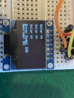
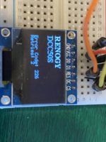
Here's mine so far;
2020-04-20 12.49.45.jpg2020-04-20 12.48.26.jpg
There's no data shown yet as it's not plugged in, but it does work. I've also got pages for Alternator status, fault codes, charging status. A pushbutton changes the page.

I plan to buy a larger OLED display and fit it in the overhead console where I have a blank panel currently, progress is a bit slow at the moment as I cant get the bits.

The cost of the arduino clone hardware is ridiculously low, like about £4 for a nano, £6 for the OLED display etc.

I can see that it may also be possible to hook this up to the Victron port in future, watch this space................
 
Last edited:
nice one, good work.

keep us posted.
 
this is great!

I'm about 1/3 of the way through my build but this will be going in for sure! I've already got a travel router with hotspot ready to go once I get all my electrics sorted over the next couple of weeks. This has made my day for the Renogy DCC50S! This thing keeps getting better and better!

I was planning on having a van server on probably a raspberry pi possibly running some docker containers. Most probably some sort of media function but most definitely graphana to see some of these stats!

I'll try and chip in when I can with some guides!
 
I went with arduino because;

It boots up very fast, like <2 seconds for the one I'm using
It is very low power when in use, as are the OLED desplays,
Both arduino and the oled have power save modes too (I've yet to work out these details
An Arduino nano 33 BLE (bluetooth low energy) has, bluetooth (obvs!) and I just found that it has an accelerometer, which among other things, can tell you if the van is level
(There's also a Wifi enabled variant of this nano)
All the hardware is tiny, and will fit in the enclosure above the rear view mirror.

I just need to find someone with a good quality 3D printer to make me a bezel of some kind.......................anyone?

I've now bought a 3.2" OLED 256x64 display as it's much more readable, and I've ordered a rotary dial encoder for page navigation.

I'll post more when I've got a worker
 
Well I'll have 200w of solar so tempted to leave the router and pi running. Will test that out tho obviously. I have a few other IoT devices so might try them also. I have 2x Chips (company now gone under) and 1x Onion Omega and 2x Onion Omega2. They also have an arduino module board so could use that.
 
Where did you buy the 3.2” OLED display from ?
One of those would be useful for a project I have in mind.

Thanks,

Pete
 
Where did you buy the 3.2” OLED display from ?
One of those would be useful for a project I have in mind.

Thanks,

Pete
I got one from Ebay for £25ish;

And I ordered another from Aliexpress for about £15, but it's not arrived yet.
 
I’m doing something very similar at the moment, ordered exactly that OLED display and seems good so far. Have been using it with a Teensy on the bench to try stuff out.

Am planning to hook it up to the Victron kit I’ve got via the VE.Direct port and aim to have a couple of OLED/rotary encoder control panels around the van to control and monitor everything.
 
@T6Jay have you got any code for this stuff yet? Or have you got the docs? That would also be handy. I'm waiting on some more insulation to come so started to tinker with some of the electrics I have planned. Solar panel going on this week so thought I'd try and get some of these stats out just to see the solar output.

I've got a tiny modbus USB that came through this week :)

The modbus mapping is an xlsx (excel) file and I can't see a way to upload it here, so I've made 3 jpgs and they are in my media.

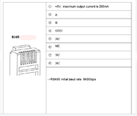
The comms parameters are; 9600,8,N,1 (9600 baud, 8 bits, No Parity, 2 Stop bits), the Renogy is node 1

The RJ45 pinout is attached

And the code........ :) you can have what I've done, I guess I would need to PM it, here's what I know;
  • I'm a C++/Arduino noob, the code is the code, feel free to criticize, improve, or bin it!
  • The code is written for a Nano 33 BLE, and may need modifications to run on any other micro. In it's present form I think it's too much for a standard Nano, or any other (UNO/Mega etc). The OLED library is massive,a more lightweight library may be better.
  • It used modified versions of some libraries, as the originals sometimes have bugs. I would need to supply you with these too.
  • The Nano 33 BLE has a built in Accelerometer, I have used this to display the van level on the OLED
  • The van level requires a 'CALIBRATE' function to set for level. The Nano 33 has no eeprom, so I have had to cobble together my own flash storage code, so that these survive a power cycle.
  • The Nano polls the Renogy DYNAMIC DATA cyclically and this works fine. It also polls the SYSTEM INFORMATION on start up, but ATM this doesn't work for some reason.
  • The Nano 33 BLE has Low Energy Bluetooth built in, so this could be used to send data to a smartphone, but I haven't implemented this.
  • The Nano 33 BLE has a 'sleep' facility (to save precious battery Ah), but I have not been able to get this working properly yet.
  • I have used a 256x64 3.2" OLED now, and use 3 pushbuttons to navigate the menu/pages. I intend to replace this with a single 'dial' control with push function, but Chinese deliveries are slow.....
DISCLAIMER ********** use this information carefully, I guess it would be possible to screw up the renogy by modifying it's parameters. I have not put any modbus writes in my code so it's safe as is. Modify it at your own risk. Also any PC connected to the renogy would also have the potential to screw things up. Please be careful.


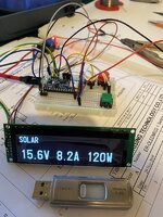
Here's how it looks now. I have pages for SOLAR, ALTERNATOR, AUX BATTERY, CHARGING STATUS, FAULTS, SETTINGS, LEVEL, SYSTEM. All accessed by a pop-up menu.
2020-05-05 22.26.48.jpg
*I'm connecting this to a modbus simulator, so please don't tell me that 15.6V x 8.2A is not 120W!

RJ45 pinout.png
 
This is great stuff. My plan is to use python with PyModbus library to pull stats and potentially to send onto MQTT and then to use in Grafana. The main bits I need are:
RJ45 pinout (cheers!)
Baud rate settings (cheers!)
Modbus mappings (I think this is the excel spreadsheet, so cheers!)

I think the rest are common to your arduino setup. I may use a RaspberryPi but will most probably end up using an Onion/Arduino hybrid thing for the IoT "smart" stuff on the van and keep seperate from any server I may have. If you could PM that code then I can reuse and would be a great help, or if you have in a GitLab repo then you could share that and I could maybe contribute back? I know quite a bit about server and network infrastructure, Pi's Im fine with but Arduino is another step for me that I haven't really played with.

Any ways I'll put what I have on GitLab for anyone to use
 
I spent last night down a rabbit hole of Home Assistant and MQTT :oops:

Got Home Assistant up and running and as I have a SolarEdge solar install in the house hooked upto that, so should be able to get House and Van Solar generation all in one page.:D Haven't got MQTT setup yet but got a few guides on using Python to send the Modbus messages onto it. I'll start another thread once I get going properly.
 
I have MQTT setup and ready to go, I still need to hook HA into it though.

I've also got my solar setup for testing and it's been pulling a few amps today through the clouds! I've got a few SBC's to try and a USB to RS485. Have fashioned a cable to connect so just need some code now.

I've had to charge my starter battery a couple of times over lockdown so hoping that solar will fill it back up!
 
I can't PM the code, it's too big. I don't know how to put it on GitHub. Email? Fileshare?
 
If you need to test your connection and rs485 converter, there's a program called Modbus Poll that's free to use for 30 days, it will grab the renogy data for you
 
Thought I'd update to this post to say I've got a working Python script. I just need to clean up the Temp registers so they will give me a negative temp when we get them. Also need to fill out some registers for the fault codes. Once I've done this I'll link to the code in another post.

Also Dellmassive let me know Renogy are releasing a BT-2 bluetooth dongle that is compatible with the Smart Lithium battery and DCC50S. Seeing as the DCC50S is RS485/MODBUS surely we can assume the Smart-Lithium battery is too? I'm sure you're aware but RS485 can have multiple addresses on one line. You just make a call to the other addresses with their specific modbus mappings. I'd be VERY interested in getting stats from the battery along with the stats for the charge controller.

I'd be interested to find out where you got the device mappings for and whether we can get the mappings for the Smart-Lithium battery then? We could poll both devices (or more if you had more than one battery) but still only have to have the one RS485 interface.
I don't know anything about the battery, but of course if it has modbusRTU and it is (or can be) 9600/8/N/2, and its' node number can be changed (I guess the default will be 1, same as the DCC50S) then it can be a slave.

I got the modbus map directly from renogy here; supportuk@renogy.com
 
Back
Top