Renogy DCC50S Display

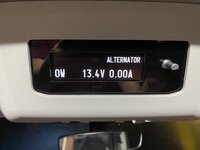
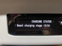
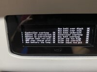
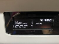
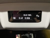
I finally managed to get the thing fitted and wired. I got an acrylic fascia laser cut for it and now just need a knob for the dial. I fitted a USB socket under the display to do any tweaks I need without de-installling the thing. Here it is;


2020-11-15 16.49.52.jpg2020-11-15 16.50.26.jpg2020-11-15 16.50.49.jpg2020-11-15 16.51.23.jpg2020-11-15 16.51.36.jpg2020-11-15 16.52.00.jpg2020-11-15 16.52.14.jpg2020-11-15 16.52.22.jpg2020-11-15 16.53.24.jpg2020-11-15 16.53.49.jpg2020-11-15 16.54.42.jpg2020-11-15 16.39.31.jpg
Boopzz I'm not sure that the Charging State data at 0x0120 is working, mine doesn't seem to have the right value. Have you found any quirks like this?
 
I’ve missed this thread purely because I don’t have a Renogy, but i love what you’ve done with this and the graphics on the oled display look amazing. I made a very basic display of my Victron solar using a Mega and a basic lcd but I think I’m going to have to revisit it after seeing this!
 
I’ve missed this thread purely because I don’t have a Renogy, but i love what you’ve done with this and the graphics on the oled display look amazing. I made a very basic display of my Victron solar using a Mega and a basic lcd but I think I’m going to have to revisit it after seeing this!
Post some pics of what you've done!

If you do get one of these 3.2" oled displays and if you need a fascia for the blank hole in a T6.1, I have 5 here, I can post one out at cost price (£5), the laser cutting price (£24) was the more or less the same for 1 piece as 6 pieces, as they all come out of an A4 sheet.

The perspex module in the pics above is made from an old number plate and hot glue.
 
I finally managed to get the thing fitted and wired. I got an acrylic fascia laser cut for it and now just need a knob for the dial. I fitted a USB socket under the display to do any tweaks I need without de-installling the thing. Here it is;


View attachment 91946View attachment 91947View attachment 91948View attachment 91949View attachment 91950View attachment 91951View attachment 91952View attachment 91953View attachment 91955View attachment 91956View attachment 91957View attachment 91958
Boopzz I'm not sure that the Charging State data at 0x0120 is working, mine doesn't seem to have the right value. Have you found any quirks like this?
Wow! That is seriously impressive. I’d love a display like that but have not got a clue what the content of the last 43 posts means!
 
Post some pics of what you've done!

If you do get one of these 3.2" oled displays and if you need a fascia for the blank hole in a T6.1, I have 5 here, I can post one out at cost price (£5), the laser cutting price (£24) was the more or less the same for 1 piece as 6 pieces, as they all come out of an A4 sheet.

The perspex module in the pics above is made from an old number plate and hot glue.

Pulled from my post on another thread. Now I'm in the process of installing my lithium battery I'm going to shuffle these round and add a "battery temperature" readout.

1605559885171.png
The case was a bit of a bodge, it was this one Yaesu Heads up Display Arduino case by ady1306 but it doesn't fit. I ended up having to print it at 110% to fit everything in, but that that left the holes in the end for connections in the wrong place, so I had to Dremel them bigger. It also left too big a gap round the screen so I printed out another copy of the case at 100% but reduced the height to 1mm and stopped the print once I'd got enough to form a border frame, almost a gasket, round the screen as in the pic. I also took a feed off the power and fitted a switch to the side so I can turn it off when sleeping. Being an Arduino, boot up is virtually instantaneous and the stats are actually in the memory of the charger so turning the Arduino off doesn't lose anything. It looks ok but I've become a bit more knowledgeable (relatively) with Fusion 360 since then so I'll probably go back and design a better enclosure when I have more time.
As for connecting, I had the right size JST lying about (think it was 1.75 or 2mm?) and you'll need an FDTI serial to USB lead. The only connections you'll need are the tx and ground from the charger, no need to connect the other 2. For power I just took the wires back to under my driver's seat where the battery, MPPT and fusebox are, and connected a buck converter. This did need setting at 5.9v rather than 5v though, otherwise there wasn't sufficient voltage to drive the arduino and screen.
 
Pulled from my post on another thread. Now I'm in the process of installing my lithium battery I'm going to shuffle these round and add a "battery temperature" readout.

View attachment 92084
The case was a bit of a bodge, it was this one Yaesu Heads up Display Arduino case by ady1306 but it doesn't fit. I ended up having to print it at 110% to fit everything in, but that that left the holes in the end for connections in the wrong place, so I had to Dremel them bigger. It also left too big a gap round the screen so I printed out another copy of the case at 100% but reduced the height to 1mm and stopped the print once I'd got enough to form a border frame, almost a gasket, round the screen as in the pic. I also took a feed off the power and fitted a switch to the side so I can turn it off when sleeping. Being an Arduino, boot up is virtually instantaneous and the stats are actually in the memory of the charger so turning the Arduino off doesn't lose anything. It looks ok but I've become a bit more knowledgeable (relatively) with Fusion 360 since then so I'll probably go back and design a better enclosure when I have more time.
As for connecting, I had the right size JST lying about (think it was 1.75 or 2mm?) and you'll need an FDTI serial to USB lead. The only connections you'll need are the tx and ground from the charger, no need to connect the other 2. For power I just took the wires back to under my driver's seat where the battery, MPPT and fusebox are, and connected a buck converter. This did need setting at 5.9v rather than 5v though, otherwise there wasn't sufficient voltage to drive the arduino and screen.
Looks good. I mean 3d printers aren't producing a perfect finish yet are they, at least not in the three figure price range? My housing is not half as professional as yours, but it's not seen at all when installed. Only the acrylic is on show.

Why did you need the RS232/USB lead? I thought the victron kit had RS232 already in the VE Direct port?

The nano33ble I used is a 3.3V device, and the RS485 can run at that voltage, also I coded a 'standby' timer in, to put the OLED and nano into sleep mode (woken by pressing/turning the dial), this keeps the power drain super low (my BM702 can't even see it).
 
@T6Jay that is really impressive! Love what youve done with it!!
Yeh I've found the same with the charge state, I seem to have a "1" for Solar and the rest are "0" but it never changes. Error codes seem to work, the only one I've had though is the Aux battery over-discharge. I have a Victron BatteryProtect which is essentially useless with this battery, im finding the internal battery BMS shuts down at ~11v from the stats whereas the batteryprotect would shut at 10v on the lithium profile. However the batteryprotect keeps the fusebox powered down until 13v.
 
@T6Jay that is really impressive! Love what youve done with it!!
Thanks Boopzz. I've been staring at the hole in the overhead console for 6 months saying to myself 'must fit display' and it's taken lockdown#2 to make me do it!
Yeh I've found the same with the charge state, I seem to have a "1" for Solar and the rest are "0" but it never changes.
What do you mean here? My understanding of 0x0120 was that the LOW BYTE would have a value from 0 to 8, indicating a 'charging mode'. So my value seems to only ever be 4 or 5 (Boost or Float). I would have expected it to sometimes (engine off, sun shining) be 2 - mppt.
I have a Victron BatteryProtect which is essentially useless with this battery, im finding the internal battery BMS shuts down at ~11v from the stats whereas the batteryprotect would shut at 10v on the lithium profile. However the batteryprotect keeps the fusebox powered down until 13v.
AGM for me, when it dies, I'm hoping lithium will be cheaper!
 
Pulled from my post on another thread. Now I'm in the process of installing my lithium battery I'm going to shuffle these round and add a "battery temperature" readout.

View attachment 92084
The case was a bit of a bodge, it was this one Yaesu Heads up Display Arduino case by ady1306 but it doesn't fit. I ended up having to print it at 110% to fit everything in, but that that left the holes in the end for connections in the wrong place, so I had to Dremel them bigger. It also left too big a gap round the screen so I printed out another copy of the case at 100% but reduced the height to 1mm and stopped the print once I'd got enough to form a border frame, almost a gasket, round the screen as in the pic. I also took a feed off the power and fitted a switch to the side so I can turn it off when sleeping. Being an Arduino, boot up is virtually instantaneous and the stats are actually in the memory of the charger so turning the Arduino off doesn't lose anything. It looks ok but I've become a bit more knowledgeable (relatively) with Fusion 360 since then so I'll probably go back and design a better enclosure when I have more time.
As for connecting, I had the right size JST lying about (think it was 1.75 or 2mm?) and you'll need an FDTI serial to USB lead. The only connections you'll need are the tx and ground from the charger, no need to connect the other 2. For power I just took the wires back to under my driver's seat where the battery, MPPT and fusebox are, and connected a buck converter. This did need setting at 5.9v rather than 5v though, otherwise there wasn't sufficient voltage to drive the arduino and screen.
You've inspired me to add 'max today' and 'total today' thanks!
 
I think my charge state is actually working. The van has normally left wifi coverage by the time the script has pulled the stat and sent it! However, yesterday my missus turned the engine on and I noticed in Grafana the value had changed! I do need to test it to see what different values I get, it will probably be easier once I get my Pi mounted in the van.

The way I read it, was the value is a 16bit register. Each bit then specifies whether a charge state is active. Below is my python code block for determining which charge state is active.
Python:
# Charge State
chargeState = instrument.read_register(256)
chargingNone = (chargeState & 0b0000000000000000) > 0
chargingSolar = (chargeState & 0b0000000000000100) > 0
chargingEqualization = (chargeState & 0b0000000000001000) > 0
chargingBoost = (chargeState & 0b0000000000010000) > 0
chargingFloat = (chargeState & 0b0000000000100000) > 0
chargingLimited = (chargeState & 0b0000000001000000) > 0
chargingAlt = (chargeState & 0b0000000010000000) > 0

If you want to try and transpose it to your code its called a bitmask
 
Last edited:
I think my charge state is actually working. The van has normally left wifi coverage by the time the script has pulled the stat and sent it! However, yesterday my missus turned the engine on and I noticed in Grafana the value had changed! I do need to test it to see what different values I get, it will probably be easier once I get my Pi mounted in the van.

The way I read it, was the value is a 16bit register. Each bit then specifies whether a charge state is active. Below is my python code block for determining which charge state is active.
Python:
# Charge State
chargeState = instrument.read_register(256)
chargingNone = (chargeState & 0b0000000000000000) > 0
chargingSolar = (chargeState & 0b0000000000000100) > 0
chargingEqualization = (chargeState & 0b0000000000001000) > 0
chargingBoost = (chargeState & 0b0000000000010000) > 0
chargingFloat = (chargeState & 0b0000000000100000) > 0
chargingLimited = (chargeState & 0b0000000001000000) > 0
chargingAlt = (chargeState & 0b0000000010000000) > 0

I think that's wrong boopz;

1605698851627.png
Look in the red circle, i think they mean 'low 8 bits' or 'low byte'
The red arrow shows a hex value, as opposed to the blue arrow, showing a bit number

My charger is always (when I see it) on 04h or 05h, and I see in the manual that 03h happens once every 28 days so I'm unlikely to see that. I'm not sure why I never see 02h though? maybe because it never need 'bulk' charging when the sun was out.

If the bits each represented a status, a value of 5 (or 3) would be two bits on together, what would that signify?
 
You are totally right, I must've had a brain fart :D. After printing the value to console it comes up with a 6 which would mean "current-limited", which it's super overcast and raining so seems logical. Just thrown in a load of quick IF statements which look like it should do the job. I'll see what it looks like in a couple of hours!

I used the bitmasks for the error codes so thats where it came from, I remember doing it late so must've been tired!
 
Why did you need the RS232/USB lead? I thought the victron kit had RS232 already in the VE Direct port?
You're absolutely right of course, think my addled brain was getting mixed up with when I was making up the Valence communication cable.

Just ordered one of those OLED screens, give me something to do at xmas.
 
I have looked at Home Assistant and looks very featureful but not quite what I want/need/looking for. NodeRED however is amazing and I know they work very well together. Yeh the SD cards weren't made for the applications that the Pi's are finding themselves in! I've bought a USB SSD drive, my thinking was no mechanical platter to get bashed about as I'm driving along! The link to the repo for the python driver is below, its a little raw and I'm in the process of having an ansible playbook that would standup docker containers on the raspberry pi. When it's a little closer I'll drop a post on these forums.

Hi, I am just new here. Do you have a little manual where to install setup the Pi.
Thanks a lot.

Great stuff so.
 
Hi, I am just new here. Do you have a little manual where to install setup the Pi.
Thanks a lot.

Great stuff so.
Home Assistant is a massive subject to itself, if you want to delve into it I’d recommend The Hookup and DrZzs YouTube channels and then work out what you actually want to do with it. There is a move away from the Pi to Odroid at the moment which I’m following.
 
Home Assistant is a massive subject to itself, if you want to delve into it I’d recommend The Hookup and DrZzs YouTube channels and then work out what you actually want to do with it. There is a move away from the Pi to Odroid at the moment which I’m following.
Hi Smart Home is not unknown to me. I am using FHEM and ESPEasys, Tasmota, some PIs, I was more interessted in the config / Arcitecture required for the Github Project.

Any special requrements? Config, Settings?

Or would a normal PI with Debian and Python enough?

Thanks
 
Hi Smart Home is not unknown to me. I am using FHEM and ESPEasys, Tasmota, some PIs, I was more interessted in the config / Arcitecture required for the Github Project.

Any special requrements? Config, Settings?

Or would a normal PI with Debian and Python enough?

Thanks
No idea I'm afraid, I don't have a Renogy
 
Back
Top