PDC Retrofit with "Auto" upgrade - Pinouts?

wheelbarrow

Member
So I bought the OE retrofit kit PDC from vagtec and also 1K8919472A upgrade kit from carsystems.eu.

This is the retrofit kit I bought:

And this is the module upgrade kit:
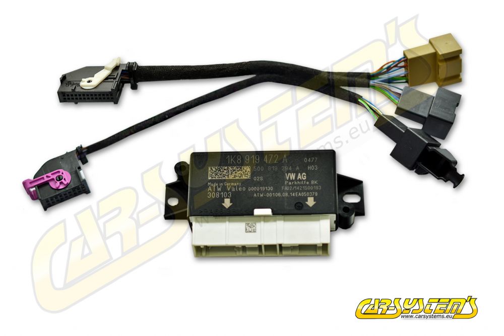
The issue I am having is that the pinouts on the upgrade module adaptor cable does not match the vag-tec loom pinouts. Not only this, but the cable colours do not match either.

Example of what I mean:

Big connector on the adaptor side (10 pins):
IMG_0095.jpgIMG_0096.jpgIMG_0097.jpg

Big connector on the loom Side (6 pins):
IMG_0107.jpgIMG_0105.jpg

And you can see that the cable colours aren't all the same either.

This is similar this for the other 2 smaller connectors:

Small connector 1 - Adaptor side (8 pins):
IMG_0090.jpgIMG_0091.jpg

Small connector 1 - loom side (6 pins):
IMG_0103.jpgIMG_0101.jpg


Small Connector 2 - Adaptor Side (10 pins):
IMG_0093.jpgIMG_0094.jpg

Small connector 2 - loom side (8 pins):
IMG_0098.jpgIMG_0099.jpg


As you can see the pins don't line up and I can't infer from the cable colours which goes where...

I am a bit lost as to where I should look next. Does anyone have any ideas or suggestion as to what to look at now? Possibly a wiring diagram, but not sure where I would find these.

Another question:

On the main loom section, there is an unterminated red, brown and yellow cable. The brown is the negative, the red is switched live, but not sure where the yellow is supposed to go to?
 
Did you get instructions with the kit ?
If not I would ask Vagtec what goes where

Normally there are two or three cables not connected as they go into an adjacent plug so after installing all the wiring you just push them into the relevant spots
 
Have reached out to Vagtec, but was thinking about this last night, the parts in either end of the looms are OEM and there fore the pinouts shouldn’t change whether the loom comes from Vagtec or carsystems.

While waiting for Vagtec to reply, I might just connect everything with the non upgraded module (I.e the one that was supplied with the loom) and see if it works.
 
OK so I installed the normal 8K module with the loom that it was supplied with.

Connected:
1) Orange/brown with Orange/brown on BCM for CAN
2) Orange/purple with Orange/green on BCM for CAN
3) Red to fuse using a fuse jumper and a 15A fuse (not sure of the requirements for this module)
4) Brown to ground
5) Front Loom to Module
6) Rear Loom to Module
7) Dash Loom to Module
8) Dash button loom to button
9) Front buzzer only

Not Connected:
1) Yellow (likely for button illumination at night)
2) Rear buzzer
3) Orange and black cables in rear loom (still not sure where these are supposed to go yet)

Then enabled the module in Gateway list.

OBD saying that the module does not respond, and when I push the button on the dash, it flashes orange on and off)

This should just work out of the box without messing with the pins surely?

No response from VagTec yet :rolleyes:
 
ok, so I found this diagram for the 8K (non upgrade) module:


schemat PDC.jpeg

Checking the photos from my connectors above, the loom pinouts look good. Not sure why the module isn't responding in ODBEleven.

I used the typical halfords lock connectors (not my favourite, but this is just a test).

Perhaps the canbus connections splice connections are swapped around or maybe they aren't connected fully?
 
All you need is the control module to be powered and the two canbus cables correctly connected and the van should be able to see the module (working or not)
Double check your 12v supply and canbus connections and make sure the plugs are fully inserted as it has to be one or the other
 
Thanks @Pauly

I was leaning towards the canbus as the module was definitely getting power. I removed the fuse and the dash button stopped doing anything.

I really don’t like those lock connectors so I’ll sort that tomorrow and go from there. Thanks again.
 
Ok so I tested continuity from the PDC module connector all the way to the BCM connector for both CAN high and CAN low. All Good.

However I still cannot see the module. I do seem to get errors with other modules when the PDC module is plugged in.

Just spoke to someone in a garage and they suggested possibly using OBDeleven may be the issue and VCDS may be needed to properly enable the PDC.

Could that be?
Try swapping the can wires round. I've come across may non OEM looms that have the can wire colours the wrong way round.
 
  • Like
Reactions: mmi
reversing the can wires crashes the whole network and all the modules go into fault, i did it once and my van wouldnt drive (DSG shutdown)
 
  • Like
Reactions: mmi
Thanks @Deaky, I thought the exact same and tried that already, with the can cables swapped, I got no response from the module and also no errors from the other modules (i.e same as the module not being connected at all).
 
QQ, I have already tapped into the CANBUS on the cable directly behind the BCM for the PFJONES towbar wiring. Does this have any bearing?

Also, could I tap the OPS CAN connections on to the CAN connections for the towbar mentioned above, or should they go straight onto the main cables that go into the BCM?

Hope that makes sense?
 
There are two canbus networks in the van, drivetrain canbus and convenience canbus, as long as you are connecting to the correct pair it wont matter where you tap in as they are common throughout the vehicle, just make sure the pair of wires are the correct colour
 
  • Like
Reactions: mmi
QQ, I have already tapped into the CANBUS on the cable directly behind the BCM for the PFJONES towbar wiring. Does this have any bearing?
I'm afraid that's wrong bus there - convenience CAN bus.
Powertrain CANbus is orange/black & orange/brown - for parking aid control unit.
 
So I have the OPS can-l going to orange/brown already, so looks like I just need to change the OPS can-h to orange/black.

Does that mean the can-l is common between the busses?
 
So I have the OPS can-l going to orange/brown already, so looks like I just need to change the OPS can-h to orange/black.

Does that mean the can-l is common between the busses?
No, it won't work properly (if at all) - the orange/brown you have belongs to convenience bus. All the CANbuses are independent twisted pairs where CAN-low is always orange/brown.
 
Back
Top