Lowering & 4-Wheel laser alignment - How I Done It -
Another constant HOT TOPIC is lowering, B14`s Elbracs etc etc
So lets take some time as see what its all about.
Steering Geometry is Very important for the life of your tyres and the safety and handling of your van. A poorly setup geometry can cause poor Tyre contact with the road, excessive trye wear and a big headache.
**************************************************
If you just dropped the van with a lowering kit of new springs and shocks then yes the geometry may be out and front camber & toe may be out.
But. . . . . . . .
This is where the 4 wheel laser alignment comes into play..
The camber, caster, toe, rake adjustments are then made to bring the geometry back into spec..(on some motors)
But... there is only a certain amount of adjustment that can be made... if your at the max of the adjustment then you may end up with a out of range Toe, camber Etc..
But.... some motors/vans only have SOME of the adjustments. The toe angle on the rear of the T6 can be adjusted but not the camber or caster. Saying that the way the rear lover wish bone is layed out the camber and caster should not change as the van is lowered. (The rear wishbone rotation point is left to right across the van and not front to back(which would change the angle))
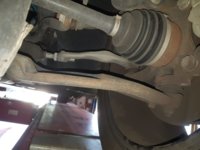
Same for the front. The toe can be adjusted from the track Rod ends. But the factory camber can caster looks to be set by the actual strut length and linkages.
So it depends if the aftermarket kit has provisions for any caster or camber adjustment. .
*********************************************************
Lets have a look at the official information taken from Elsawin.

Test prerequisites
l Check suspension, wheel bearings, steering and steering linkage for excessive play and damage.
l Tread depth difference does not exceed 2 mm on one axle.
l Check prescribed inflation pressure of tyres.
l Ensure vehicle is unladen.
l Fuel tank must be full.
l The spare tyre and vehicle tool set must be secured at the specified locations in the vehicle.
l The washer fluid reservoir must be full.
l When checking wheel alignment, ensure that sliding plates and turn tables are not touching end stop.
 Note
Note
t To allow running gear to »fully settle«, wheel alignment should not be checked before the vehicle has completed 1000 to 2000 km.
t When making adjustments, try to adhere to the relevant specifications precisely.
t Refer to the user's manual of the equipment maker for proper attachment and adjustment of the measuring devices.
t Wheel alignment platforms and alignment units and computers should be checked and adjusted as necessary during inspection and maintenance at least once per year!
t Handle these highly sensitive measuring devices carefully and conscientiously.
*********************************************************************
Now Lets look at the Actual Front & Rear setup.
FRONT:
Camber & Caster is not adjustable.!
Adjusting camber at front wheels
 Note
Note
t It is not possible to adjust camber of front wheels!
t If the measured values are outside the allowed tolerance, camber can only be corrected by renewing the affected axle components.
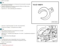
Adjusting front axle toe
Required special tools, test and measuring devices as well as auxiliary items
Before carrying out the adjustments, turn the steering to the centre position as requested by the wheel alignment computer.
t Procedure for adjusting toe on front axle is explained for left track rod. Setting must be performed on right side as well if necessary.
– Loosen lock nut -1- while counterholding track rod ball joint -4-.
REAR:
Camber & Caster is not adjustable.!
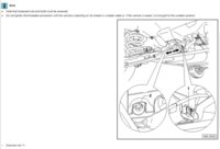
Adjusting toe at rear axle
Required special tools, test and measuring devices as well as auxiliary items
t Torque wrench -V.A.G 1332/-
Note
t Note that loosened nuts and bolts must be renewed.
t Do not tighten the threaded connection until the vehicle is standing on its wheels in unladen state or, if the vehicle is raised, it is brought to the unladen position.
Unscrew nut -1-.
– Remove eccentric bolt and renew with new eccentric bolt → Electronic Parts Catalogue (ETKA).
– Do not tighten eccentric bolt yet.
– Turn eccentric bolt -2- until specification is attained.
– Tighten nut -1-.
**********************************************************************************
So thats the Offical word on the situaltion . . . . . . . . But what does that mean in real life?
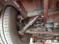
well lets look at our T6 as an example. its a T32 PV with factory sportline suspension.
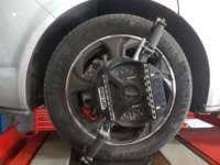
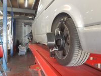
we put it on the laser alignment machine to see what the Factory set-up was and get a baseline . . . . The results were disappointing to say the least.
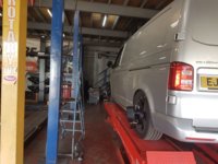
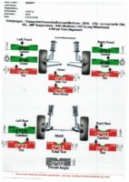
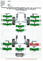
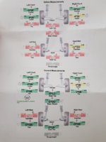
The results showed that the factory setup was out slightly . . . . . The recomendation was to have the rear toe adjusted.
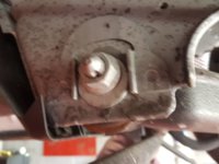
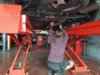
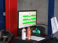
This is how they done it, as per Elsawin the rear wishbone locking nut was loosened and the cam adjuster was tweeked, one way, then the other whilst constantly watching the computer screen at the live readout. first onside, then the other, then back again.
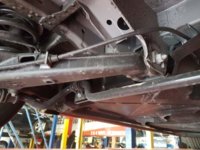
.
The results were live and shown on the computer screen . . . .
.
8pics limit so continued below . . . . . .
More info over here > Dellmassive`s -- "how I Done It" -- Thread
.
Another constant HOT TOPIC is lowering, B14`s Elbracs etc etc
So lets take some time as see what its all about.
Steering Geometry is Very important for the life of your tyres and the safety and handling of your van. A poorly setup geometry can cause poor Tyre contact with the road, excessive trye wear and a big headache.
**************************************************
If you just dropped the van with a lowering kit of new springs and shocks then yes the geometry may be out and front camber & toe may be out.
But. . . . . . . .
This is where the 4 wheel laser alignment comes into play..
The camber, caster, toe, rake adjustments are then made to bring the geometry back into spec..(on some motors)
But... there is only a certain amount of adjustment that can be made... if your at the max of the adjustment then you may end up with a out of range Toe, camber Etc..
But.... some motors/vans only have SOME of the adjustments. The toe angle on the rear of the T6 can be adjusted but not the camber or caster. Saying that the way the rear lover wish bone is layed out the camber and caster should not change as the van is lowered. (The rear wishbone rotation point is left to right across the van and not front to back(which would change the angle))
Same for the front. The toe can be adjusted from the track Rod ends. But the factory camber can caster looks to be set by the actual strut length and linkages.
So it depends if the aftermarket kit has provisions for any caster or camber adjustment. .
*********************************************************
Lets have a look at the official information taken from Elsawin.

Test prerequisites
l Check suspension, wheel bearings, steering and steering linkage for excessive play and damage.
l Tread depth difference does not exceed 2 mm on one axle.
l Check prescribed inflation pressure of tyres.
l Ensure vehicle is unladen.
l Fuel tank must be full.
l The spare tyre and vehicle tool set must be secured at the specified locations in the vehicle.
l The washer fluid reservoir must be full.
l When checking wheel alignment, ensure that sliding plates and turn tables are not touching end stop.

t To allow running gear to »fully settle«, wheel alignment should not be checked before the vehicle has completed 1000 to 2000 km.
t When making adjustments, try to adhere to the relevant specifications precisely.
t Refer to the user's manual of the equipment maker for proper attachment and adjustment of the measuring devices.
t Wheel alignment platforms and alignment units and computers should be checked and adjusted as necessary during inspection and maintenance at least once per year!
t Handle these highly sensitive measuring devices carefully and conscientiously.
*********************************************************************
Now Lets look at the Actual Front & Rear setup.
FRONT:
Camber & Caster is not adjustable.!
Adjusting camber at front wheels

t It is not possible to adjust camber of front wheels!
t If the measured values are outside the allowed tolerance, camber can only be corrected by renewing the affected axle components.

Adjusting front axle toe
Required special tools, test and measuring devices as well as auxiliary items
Before carrying out the adjustments, turn the steering to the centre position as requested by the wheel alignment computer.
t Procedure for adjusting toe on front axle is explained for left track rod. Setting must be performed on right side as well if necessary.
– Loosen lock nut -1- while counterholding track rod ball joint -4-.
REAR:
Camber & Caster is not adjustable.!

Adjusting toe at rear axle
Required special tools, test and measuring devices as well as auxiliary items
t Torque wrench -V.A.G 1332/-
Note
t Note that loosened nuts and bolts must be renewed.
t Do not tighten the threaded connection until the vehicle is standing on its wheels in unladen state or, if the vehicle is raised, it is brought to the unladen position.
Unscrew nut -1-.
– Remove eccentric bolt and renew with new eccentric bolt → Electronic Parts Catalogue (ETKA).
– Do not tighten eccentric bolt yet.
– Turn eccentric bolt -2- until specification is attained.
– Tighten nut -1-.
**********************************************************************************
So thats the Offical word on the situaltion . . . . . . . . But what does that mean in real life?
well lets look at our T6 as an example. its a T32 PV with factory sportline suspension.
we put it on the laser alignment machine to see what the Factory set-up was and get a baseline . . . . The results were disappointing to say the least.


The results showed that the factory setup was out slightly . . . . . The recomendation was to have the rear toe adjusted.
This is how they done it, as per Elsawin the rear wishbone locking nut was loosened and the cam adjuster was tweeked, one way, then the other whilst constantly watching the computer screen at the live readout. first onside, then the other, then back again.

.

The results were live and shown on the computer screen . . . .

.
8pics limit so continued below . . . . . .
More info over here > Dellmassive`s -- "how I Done It" -- Thread
.
Last edited:

