Do I need a (240v) feed fuse for victron charger?

Deaks

Senior Member
VIP Member
T6 Pro
So I’m running all the cables for the conversion and all is going well, despite always needing more cable!!

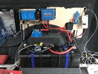
The test install of the victron kit has been successful, so now I need to put the finish panel behind and re fix it all back. The space to the right of the MPTT solar controller is for the victron Orion dc dc charger.

as you can see, I have installed a Victron 30 amp mains charger, that has its own dedicated 6 amp RCBO in the EHU consumer unit in the engine compartment battery area.

My question is, do I need to keep the 13 amp plug on the cable (has a 5 amp fuse fitted) and then have to find space for a 13 amp socket, or can I direct wire into the feed cable from the consumer unit. ACB0F870-102F-4FD5-BA71-167FDFE8F22E.jpeg
Thanks in advance

Deaks :)
 
if you have the - dedicated 6 amp RCBO in the EHU consumer unit.

then yes you can cut the plug off and hard wire it. ( as you are still fused low enough @ 6A )

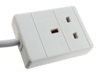
or just fit one of these..

1597586138694.png


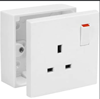
or one of these . . .


1597586185434.png
 
the install is coming along very nicely.

you should be able to power a coffee machine from that . . . . no problem.


wheres the inverter?

and DC-Dc charger?

some pics of the panels would be nice . . . .


you need to start your own build thread too . . .

this level of power and install quality will help out other members . . . .


when you get a chance start you build thread over here:


.
 
Thanks for confirming what I was hoping would be ok.

The inverter position is still a bit up in the air, it’s a pretty big unit.
im seeing Matt @ infinity Customs tomorrow to hopefully do the CAD drawings for the kitchen. I’m hoping we can decide together on the best place for it to go.

The DC DC charger will go to the right of the solar charger. Today I have Finished running the feed cable ( and ignition switched live feed) from the engine bay into the ‘Victron area’.

It’s surprising how much cable is needed, and how long it all takes.

I have been taking pictures as I go, as I really do want to start a build thread. I’ll try and get started on that this week I think.

I’m looking forward to getting all the WiFi and lighting installed soon. I think I might also do a Pi based automation and Victron monitoring system as the van will always be online with an unlimited data connection via the Teltonica 4g router.
I have the heater working over MQTT, but would like to get some voice activation with Amazon Echo.

Deaks
 
I always fit a socket, helps with fault isolation and component swapping. Whats the thinking behind the solar breaker Deaks?
 
The solar breaker is in its temp home at the moment. I thought it would be a good idea to be able to isolate the panel given that they are normally providing some output.
It will be fixed inside the furniture when that goes in (soon I hope).
Deaks :)
 
Beats throwing a tarp over it when working on the solar charger ;)
 
Just be aware of how hot the Orion DCDC can get (very!).

I originally had mine bolted to a plywood board under the passenger seat but am in the process of redoing the mounting under the seat to make sure it’s got more room and the cooling fins are mostly uncovered.
 
THanks for the heads up on the orion heat. I have now modded the mounting of this and the MPTT controller, so they both sit off of the back board by 25mm, sonthe fins can dissapate the heat (hopefully).

Deaks :cool:
 
Thanks for confirming what I was hoping would be ok.

The inverter position is still a bit up in the air, it’s a pretty big unit.
im seeing Matt @ infinity Customs tomorrow to hopefully do the CAD drawings for the kitchen. I’m hoping we can decide together on the best place for it to go.

The DC DC charger will go to the right of the solar charger. Today I have Finished running the feed cable ( and ignition switched live feed) from the engine bay into the ‘Victron area’.

It’s surprising how much cable is needed, and how long it all takes.

I have been taking pictures as I go, as I really do want to start a build thread. I’ll try and get started on that this week I think.

I’m looking forward to getting all the WiFi and lighting installed soon. I think I might also do a Pi based automation and Victron monitoring system as the van will always be online with an unlimited data connection via the Teltonica 4g router.
I have the heater working over MQTT, but would like to get some voice activation with Amazon Echo.

Deaks
Deaks - I have a full Victron setup and interested in your WiFi options. How do you plan to set this up? ( If you don’t mind me asking).
 
Just be aware of how hot the Orion DCDC can get (very!).

I originally had mine bolted to a plywood board under the passenger seat but am in the process of redoing the mounting under the seat to make sure it’s got more room and the cooling fins are mostly uncovered.
Spot on!..... people don’t realise that the 12/12/30 Orion DC/DC is a 40Amp Full rated charger!, it is only derated to 30A at an ambient temp of 40 degree’s!
 
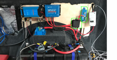
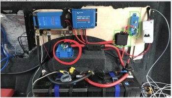
@Deaks or anyone else who can help.. what are the two items I've circled? Is one a junction box and the other a positive bus bar? I assume it's to avoid having to many connections on the positive battery terminal? I must admit this time around I'm probably going to need 5 cables on the leisure battery terminal so will probably need something similar to this. Also with the 240V victron charger (I know it's got built in fuse protection) does anyone chuck an inline fuse in the positive cable to the leisure battery? I'm going to have my charger where it is in Deaks example but it will be a long cable run (LWB) to the passenger seat where the leisure battery is.
1644748889957.png
 
@Deaks or anyone else who can help.. what are the two items I've circled? Is one a junction box and the other a positive bus bar? I assume it's to avoid having to many connections on the positive battery terminal? I must admit this time around I'm probably going to need 5 cables on the leisure battery terminal so will probably need something similar to this. Also with the 240V victron charger (I know it's got built in fuse protection) does anyone chuck an inline fuse in the positive cable to the leisure battery? I'm going to have my charger where it is in Deaks example but it will be a long cable run (LWB) to the passenger seat where the leisure battery is.
View attachment 145697
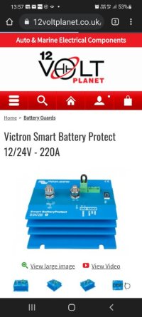
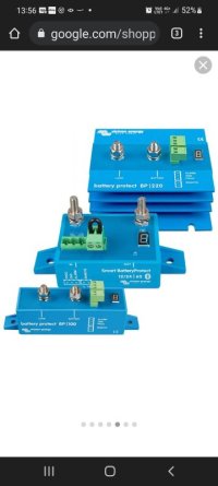
To me the black box looks like a fuse box/ distribution box, and the Victron kit looks like a smart battery protect.
 
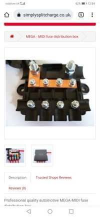
Yeh, bit more googling and I think I figured it out. Like one of the below? Am I right in thinking I can do one 10mm2 cable from the battery to this. Then connect the b2b charger input, output to both fuses boxes (for lights firdge etc etc) to the free posts on the distribution box. Then I'll just go straight to the battery terminal with the 240v battery charger and votronic temperature sensor. Thus reducing the need for 5 cables on the battery terminal to 3.

Screenshot_20220213_120441_com.android.chrome.jpg
 
The smart battery protects are needed in this system because the V1 black Valence battery s he's using doesn't have an internal BMS that's active all the time....

So they are needed to save the batterys from low voltage and will switch off the loads at a programme point.... Running lithium dead flat will knacker them. (Modern battery BMS have this feature built in)

Also recommend for lead based batterys.

Not needed for more modern lithium battery s that have full featured internal BMS.
 
Sorry to hijack this post. I have a victron 12v25a blue smart charger and I was planning on wiring the mains cable direct to the 6a rcbo in the cu until I noticed the 13a fuse in the plug.

I'm guessing I'd now have to change the 6a type c rcbo for a 13a one?
 
Sorry to hijack this post. I have a victron 12v25a blue smart charger and I was planning on wiring the mains cable direct to the 6a rcbo in the cu until I noticed the 13a fuse in the plug.

I'm guessing I'd now have to change the 6a type c rcbo for a 13a one?
You should be fine wiring direct to the 6a rcbo.
 
Back
Top