fwiw. . .
I've been using these guys for proper cable. . .

.

...
to spain.

I've been using these guys for proper cable. . .
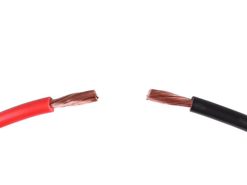
Extra Flexible PVC Battery Cable - 16mm² 110A
110A 16mm² extra flexible PVC battery/welding cable for auto, marine & leisure applications. Available in red or black.
www.12voltplanet.co.uk
.
...
to spain.


