You are using an out of date browser. It may not display this or other websites correctly.
You should upgrade or use an alternative browser.
You should upgrade or use an alternative browser.
Solar Cable Length query
- Thread starter winstonedd
- Start date
this is helpfulThe manual should indicate cable and fuse size. Size fuse to protect cables, depends on installation method and type of cable, but 4mm will be around 40A (likely more in real life), so I'd put a 35 or 40 a fuse in. See Here

same principle applies. If the Renology is outputting 50A, you need to size cables to carry 50A minimum and then fuse smaller than cable capacity so fuse 'blows' before cable burns out. There are other factors to take into account on cable size, volt drop, installation method, diversity etc for cable sizing (all affects current carrying capacity) but no need to go into all that here.this is helpfulalthough i meant the fuses from the renogy unit to the car and leisure batteries
im assuming 60AH for the 50A DC unit. will go through manual later


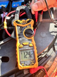
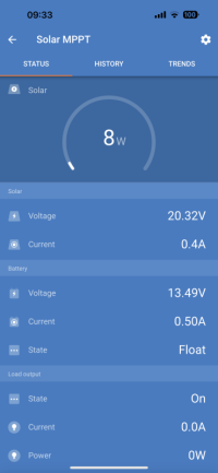
Perplexed of Dursley here. My MPPT is reading a battery voltage of 13.6v while connected to the Main Battery and quite rightly is in Float mode. The BM6 on the MB is however reading 12.46v which aligns to the multimeter reading.
Given the cable run is 1.5m I thought i might have a volt drop issue but was surprised at the voltage difference. However.....
Removed the in line fuse next to the MB and the MPPT side is 13.5v and the other 12.46v. The fuse is good and so is continuity to the end of the cable feed from MPPT to battery terminal.
If the issue is not cable length nor cable continuity why am i not seeing one common voltage? The Solar as a result of the higher voltage is only trickle charging. if there is a battery load (which there is bound to be) then surely the MPPT output reading should be 12.46v.
You're assuming here that both measurements are correct, it might simply be that one of them isn't accurately calibrated.
What MPPT are you using?
What MPPT are you using?
iam using a multimeter to correlate the readings on the battery, the monitor and the Victron MPPT not just taking the readings for granted. WeirdYou're assuming here that both measurements are correct, it might simply be that one of them isn't accurately calibrated.
What MPPT are you using?
That is weird and yes I'd trust measurements from Victron, especially if your multimeter shows the same reading on both.
Do you have a diagram of your setup?
You mention a cable run of 1.5m - is that between the Main Battery and MPPT?
What cross section is that cable? And what charge current? Might be interesting to work out what the voltage drop would be.
The mental map I have from your description is this:
BM6 <-> Main Battery <-> Inline Fuse <-> 1.5m cable <-> Victron MPPT <-> Panels
This is my next job @dcpen43, I've read and read loads on here and it seems a pretty straightforward job adding the Mppt. I don't want mine to be permanent so intend to just have the connects so I can hook it up when needed.Finished my solar fit today with the cables fed outside the habitation area to two predrilled grommeted holes in the RHS barn door cill. No idea what their original purpose was. Cables feed above the wardrobe and along the back of the rack and pop out just before the drivers B pillar. My Victron MPPT is mounted behind the driver's seat allowing a short output run to the LB under the driver. All working good.
On your point about heaters. Got a tip to but a small AC Ceramic heater so that I don't need to burn my diesel when on EHU.
@roadtripper thankyou for taking an interest in this.Do you have a diagram of your setup?
You mention a cable run of 1.5m - is that between the Main Battery and MPPT?
What cross section is that cable? And what charge current? Might be interesting to work out what the voltage drop would be.
The mental map I have from your description is this:
BM6 <-> Main Battery <-> Inline Fuse <-> 1.5m cable <-> Victron MPPT <-> Panels
A thought has popped into my mind about my wiring which i will explore tomorrow morning and come back to you with some pictures.
the MPPT output feeds a pole switch allowing me to switch output between LB and MB. i want to check the two circuits are isolated from one another
If you have a changeover switch like that you might also want to double check it is a "break before make" otherwise everytime you change over there is a moment where you are directly connecting both batteries and with a big differential you could get substantial current flow.
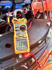
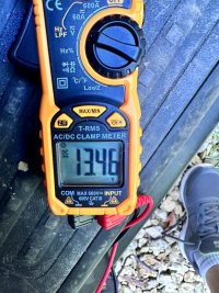
no its a Heschen switch and i have to physically plug the sae cable into the port. anyway took some readings today. 13.46v at the MPPT and in line fuse so negligible volt drop attributed to AWG10 cable. 12.42v on the battery side of the in line fuse.If you have a changeover switch like that you might also want to double check it is a "break before make" otherwise everytime you change over there is a moment where you are directly connecting both batteries and with a big differential you could get substantial current flow.
just switched over to the leisure battery and it acts in a similar fashion showing a volt differential. have the benefit of the victron shunt on the LB so can track current and its trickle charging.
wonder whether the van BMS is simply doing its job and limiting charge.
There isn't a van BMS in a position to control any charge (it does that simply by controlling the alternator) and your cable goes direct to the battery.
Have you checked the voltage at the terminals of the MPPT when everything is connected? I can understand why it would be a different voltage when it's just floating and not connected but not otherwise.
You still haven't mentioned the charge current but an estimate of 1v drop at 5a is a 5w loss, so about 0.2ohms, that seems high but not impossible and wouldn't really warm things up. With 10awg over 1.5m though the expected drop would be about 0.05v
I'm wondering if you have a bit of corrosion or something not seated right in your run, 0.2ohms isn't a lot in those conditions
There isn't a van BMS in a position to control any charge (it does that simply by controlling the alternator) and your cable goes direct to the battery.
Have you checked the voltage at the terminals of the MPPT when everything is connected? I can understand why it would be a different voltage when it's just floating and not connected but not otherwise.
You still haven't mentioned the charge current but an estimate of 1v drop at 5a is a 5w loss, so about 0.2ohms, that seems high but not impossible and wouldn't really warm things up. With 10awg over 1.5m though the expected drop would be about 0.05v
I'm wondering if you have a bit of corrosion or something not seated right in your run, 0.2ohms isn't a lot in those
first thing i did was to check the MPPT direct as in the pic to give me a volt drop reference. Charge current lowThere isn't a van BMS in a position to control any charge (it does that simply by controlling the alternator) and your cable goes direct to the battery.
Have you checked the voltage at the terminals of the MPPT when everything is connected? I can understand why it would be a different voltage when it's just floating and not connected but not otherwise.
You still haven't mentioned the charge current but an estimate of 1v drop at 5a is a 5w loss, so about 0.2ohms, that seems high but not impossible and wouldn't really warm things up. With 10awg over 1.5m though the expected drop would be about 0.05v
I'm wondering if you have a bit of corrosion or something not seated right in your run, 0.2ohms isn't a lot in those conditions
The reason for my previous comment was with an understanding that the Van Bms carried a historic log of current in and out of the battery as the Victron shunt does, limiting charge to the battery.
I have my setup for the negative from the MPPT connected to the ground not neg. of the battery.
its not the end of the world as i still have a trickle charge to the MB when not in use (for the summer at least)
Yes the van ECU tracks the state of the battery at all times via the negative shunt but it has no way of actively limiting the charge - it has no need to as the only charger it knows about is the alternator. If it doesn't think the battery needs charge, it doesn't enable the alternator.
So if you've double checked the voltage at the MPPT when it's fully connected to the starter battery with the multimeter and it agrees, but the measurements from the BM2 and multimeter under the same conditions (fully connected) agree as lower then the only way that can happen is with resistance in the circuit, it wouldn't take much only 2ohms.
I suspect when you checked for continuity that you just had your meter on buzzer - and at this point quite low resistance would trigger the buzzer.
So I would try and measure the true resistance of the connections as best you can to try and find that 2 ohms. My suspicion right now is the fuse and it's holder. Again 2 ohms would trigger a multimeter continuity test so measure it on resistance.
ok my choice of words. the ECU is actively preventing charge to the battery based on SoC? if you dont use the battery for the starter motor etc often then charge capacity is adapted to extend battery life?Yes the van ECU tracks the state of the battery at all times via the negative shunt but it has no way of actively limiting the charge - it has no need to as the only charger it knows about is the alternator. If it doesn't think the battery needs charge, it doesn't enable the alternator.
will put the VCDS on and see whether the BEM data is coded correctly. the garage said they did this when they put a new battery in in Feb.
Am i the only one who longs for the days when you could tinker with the car knowing what you were doing
There is nothing in the van electrics or any setting in VCDS that will actively stop the starter battery charging from your MPPT.
How your MPPT behaves is solely a function of the MPPT settings and the wiring between it and the battery.
How your MPPT behaves is solely a function of the MPPT settings and the wiring between it and the battery.
yep but the VCDS will tell me what data the ECU is holding on the battery and as the attachment shows the garage did not do any codingThere is nothing in the van electrics or any setting in VCDS that will actively stop the starter battery charging from your MPPT.
How your MPPT behaves is solely a function of the MPPT settings and the wiring between it and the battery.
thanks for your input @roadtripper
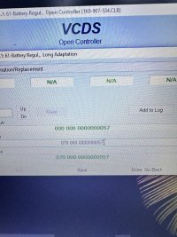
Even if you don't set any specifics the ECU will still learn the general characteristics of the battery after about 10 cycles. If you've reset the data by updating the serial it will need to go through that learning period again so you might find items like start stop don't engage until then and charging is not optimal. I'd wait till that has settled down before digging into the solar charging some more.
Similar threads
- Replies
- 6
- Views
- 648
- Replies
- 0
- Views
- 279
- Replies
- 8
- Views
- 365
- Replies
- 6
- Views
- 868
- Replies
- 1
- Views
- 891
