Nightmare trying to hardwire Blackvue Lipo

Ethan Andrews

Member
VIP Member
T6 Pro
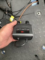
I am actually wondering if my Blackvue B124-X is faulty.

I can charge it from the cigarette lighter.

But using the mini blade fuse adapter nothing.

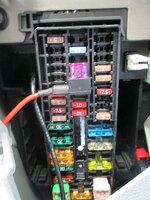
I found an ignition switched 12 volt feed as shown in photo. But it is as if the feed on the supplied piggyback cable is open circuit. As no charge to the battery.

First I questioned my earth. But now I am using the OEM earth point under the seat. I have continuity from the earth point to the end of the cable.

It’s the same process for the positive. I have even replaced the piggy back cable with a new one.

But whatever I do. I cannot get 12 volts to the battery. It’s as if there is a blocking diode somewhere. But there is not.

Confused to say the least.
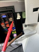
548BE11F-3FC0-4768-B393-6817432F336F.jpeg
 
The fuse you are measuring in your photo is the starter feed so only live whilst starting, use the centre row.
 
I put mine where the 7.5A fuse is. Comes on with the Ignition and off with it off. Works fine.
View attachment 74421

Thanks I will try that. But my multimeter showed it as permanently live. Maybe it’s the answer with a secret switch somewhere. As I currently get in and then switch on the power by reaching under the seat. As in this photo with seat removed.

68A69893-2410-47D7-B24B-6EB0A9C0CD39.jpeg
 
As others have said, use the centre row of fuses as these are switched ignition feeds (Only on when ignition is on). Also make sure you have the piggy back fuse the right way round, tail to the left as shown in the photo above.
 
not teaching you to suck eggs but you have got 2 fuses in the piggyback? The original from the slot you’re using and a new one for the dashcam?
 
As others have said, use the centre row of fuses as these are switched ignition feeds (Only on when ignition is on). Also make sure you have the piggy back fuse the right way round, tail to the left as shown in the photo above.


Thank you. It is to the left fortunately. But is this just best practice in terms of being able to read the fuse?
 
Thank you. It is to the left fortunately. But is this just best practice in terms of being able to read the fuse?
No, if you put it in the other way your piggybacked circuit will not be fused correctly
 
Last edited:
not teaching you to suck eggs but you have got 2 fuses in the piggyback? The original from the slot you’re using and a new one for the dashcam?


Ahhh! I am glad you made me suck an egg!

No I only had the original one in there

That may explain why it seemed open circuit. Thank you Deaky you are a legend!

So if I put two fuses in of the same value. This will be fine. I just presumed the two slots were for a series circuit. i.e. Adding for example 2 x 7.5A ‘s to culminate 15A in place of not having a 15A fuse to hand.

This is obviously not the case. No fuse for the extension circuit = open circuit. And now I know why the kit came with extra fuses. Although they were the micro variety. So no good for me anyway.

I suppose it comes down to what I used to tell people. RTFIM! - Read the @#£&ing instruction manual!
 
Thank you. It is to the left fortunately. But is this just best practice in terms of being able to read the fuse?
If you install it the wrong way round it won’t work. I struggled to get this at first until I drew out the circuit and how it all connected. To be certain stick a meter on the end of the tail when the ign is on and check for 12v at that point
 
Ahhh! I am glad you made me suck an egg!

No I only had the original one in there

That may explain why it seemed open circuit. Thank you Deaky you are a legend!

So if I put two fuses in of the same value. This will be fine. I just presumed the two slots were for a series circuit. i.e. Adding for example 2 x 7.5A ‘s to culminate 15A in place of not having a 15A fuse to hand.

This is obviously not the case. No fuse for the extension circuit = open circuit. And now I know why the kit came with extra fuses. Although they were the micro variety. So no good for me anyway.

I suppose it comes down to what I used to tell people. RTFIM! - Read the @#£&ing instruction manual!
Glad your sorted mate :thumbsup:


If you install it the wrong way round it won’t work. I struggled to get this at first until I drew out the circuit and how it all connected. To be certain stick a meter on the end of the tail when the ign is on and check for 12v at that point

it will work, but your new circuit will be connected after the fuse of the original circuit
 
If you install it the wrong way round it won’t work. I struggled to get this at first until I drew out the circuit and how it all connected. To be certain stick a meter on the end of the tail when the ign is on and check for 12v at that point
Thank you
 
Glad your sorted mate :thumbsup:


it will work, but your new circuit will be connected after the fuse of the original circuit
Quite right Deaky! I was thinking of my setup where I used a spare (unused) fuse slot so I didn’t bother to put the second fuse in place (or should that be the first fuse). As I only have a fuse on the side with the tail, it won’t work the wrong way round. If I put the other fuse in it would but as you say if it’s as the wrong way it would be after the primary fuse.
 
Glad your sorted mate :thumbsup:


it will work, but your new circuit will be connected after the fuse of the original circuit

Well it was my stupidity over the fuses. And thanks again to you Deaky and everyone else input it is now working as it should be as ignition live only. I used the central 7.5A as Urban Fox reccomended.

Thanks again everyone.

41CD33FD-13E5-403B-83DF-323EE3125260.png

4D46F223-9782-47C9-BC5A-F4AB686BA212.png
 
The fuse I used was the one that came with the piggyback adaptor and was 3A along with the original 7.5A.
Nice to see you got it working.
I stayed with 7.5A as in the Blackvue hardwire option it allows you to hardwire the battery up to 9A. And certainly charges or rather keeps the battery topped right up ba the lower amperage cigarette lighter.
 
Back
Top