Exciting, post post your results here. =)I’ll start by saying a big thank you to @Dellmassive for doing all the research, it has helped me make the decision on what panel would suit my needs.
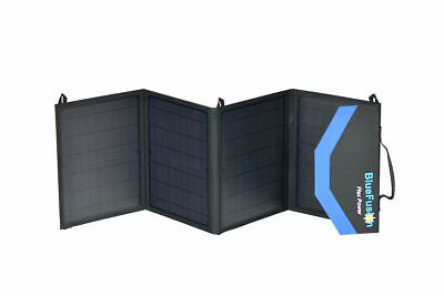
After reading this thread last week, I ordered a Blue Fusion 50W portable panel. It arrived today
First thing I did was remove the cable with the battery clips from the controller. I replaced it with a 12V cigarette adapter after I cut off the socket end and tinned the cable ends. I really wanted to do a full on test but as it didn’t arrive until after 3PM there wasn’t really much of the day left....but I had a go.
Battery cable removed from controller here:
View attachment 70319
Cut socket off of 12v plug/socket extension and tinned the cable ends:
View attachment 70322
View attachment 70320
And connected to the controller to give me this:
View attachment 70323
I still have the cable with the clips on it and can swap it back anytime i might need to.
For now this allows me to connect the panels to either my Starter battery or my Leisure battery as I have a 12v socket connected to both. The cable on the 12v lead is long enough to reach from the dash into the rear of the van to where my 12V Leisure socket is and it is also long enough to allow the panels to be placed on the roof and still connect to either of my 12v sockets. As I also have a CTEK 250SE I have the option to connect directly to this (without the controller) at some point in future should I ever need to do that.
For me this is a very versatile solution and should allow me to charge either battery as the main priority and using the CTEK, overflow from the starter into the leisure once the starter is charged (I want to test this tomorrow).
Priority for now is the Starter as the van isn’t being used much and the starter slowly drains.....
Despite there being little of the day left I thought I’d give it a go so I connected the 12v plug into the dash socket and set the battery type on the controller and left the panels on the dash for a few hours (it is still out there now as it happens).
Here is the output from the BM2 on the Starter battery. I connected it shortly after 4PM, It produced a decent charge around 4.30PM as the sun was out but as the sun faded so the charge has diminished. Nevertheless I’m confident it will do what I need it to .
View attachment 70344
This is it laid out on the dash:
View attachment 70352
Further updates tomorrow assuming decent weather")
You are using an out of date browser. It may not display this or other websites correctly.
You should upgrade or use an alternative browser.
You should upgrade or use an alternative browser.
[Guide] Mobile Solar Panels ? . . . - How I Did It -
- Thread starter Dellmassive
- Start date

Exciting too. . . . , looking at your BM2 printout you had the van on EHU charger until you connected the solar? (What size charger,)No idea why, but I seemed to post this in the wrong thread, so I’ll try again!
In order to try and extend my time ‘off grid’ I wanted a quick and simple mobile solar solution. I went for a 50w folding solar panel with regulator from Bluefusion. It’s a PWM regulator and has a USB out port.
It was listed at £92 on eBay, but they had a savings code, and it came in at £85. As per @Dellmassive , it’s normally about £2 per watt, so at £85, it was a good buy.
It’s amazingly small and light. Not a lot bigger than a couple of magazines stacked up.
It’s fitted with insulated croc clips, but I’ve changed this for a fused (fuse is IMPORTANT) cigarette plug so I can plug it into the sockets for the leisure or starter battery.
Fits nicely on the dash, or on the windscreen for maximum gain. I can actually fit my internal blind, and the panel will still see the sky.
You can see from the BM2 read out that the voltage spiked up to 13.9v about 10:30am (no load on the battery). I put the fridge on (72w compressor fridge) at about 10:45am and it was warm, so had to work hard. Voltage dipped to 12.6v under load. When the fridge was cool, the compressor turned off, and the voltage crept up to 13.v and back to 12.6v when the compressor was on.
Under good sunlight, it seemed to be keeping up with the fridge. I unplugged the solar panel at about 13:30, and left the fridge on, and you can see a downward trajectory on the graph as the battery drained.
I’ll get an ammeter on it at some point, but overall really pleased for a simple, cheap and quick solution.
PS, I know it desperately needs a wash!
View attachment 70357
View attachment 70358
View attachment 70359
View attachment 70360
View attachment 70361
View attachment 70362
View attachment 70363
Post your results after a full days sun if you can. =)
Exciting too. . . . , looking at your BM2 printout you had the van on EHU charger until you connected the solar? (What size charger,)
Post your results after a full days sun if you can. =)
No it was just parked up with no hookup. It was just laid up but with the 12v system turned off, and the fridge off!
Partial test completed today. I connected the solar panel up around 7AM this morning. It was very overcast so I wasn’t expecting much to be honest. The sun did come out to play and by around 10:30 the Starter was charged enough so that the CTEK kicked in to charge the Leisure battery. I wanted to leave it for a full day but had to go out shopping so that interrupted the test. I connected the solar again around 13:45 and left it for the rest of the day. I started with it on the roof this morning, the dash the early part of this afternoon and then moved it to the front of the screen shortly after 15:00. By 17:00 the panel was in the shade so it wasn’t doing much by then.Exciting, post post your results here. =)
I took a voltage measurement on the output of the panel when it was in full sun and was reading around 19V.
I think this is showing the CTEK kicking in once the Starter reaches 13.1V, voltage then drops as it charges the leisure battery so CTEK turns off again And starter voltage rises again

And this is the starter over the day. You can see in the period between 11 & 12 where the CTEK is kicking in and out and charging through to the leisure battery. The two big peaks are my trip to the shops. The dip just after 3 is when I moved it from dash to outside on the front of the screen.

If the suns comes out to play tomorrow I’ll try and get a full days test in.
I also want to connect the panel directly to the solar input on the CTEK at some stage but will need to make up some cables to do that so it will be a while as i need to order some bits and pieces to make the cables and find the time to get under the front seat to access the CTEK. I plan to add a socket connector to the CTEK on a short lead so I can easily plug the panel in and out as I need it.
Partial test completed today. I connected the solar panel up around 7AM this morning. It was very overcast so I wasn’t expecting much to be honest. The sun did come out to play and by around 10:30 the Starter was charged enough so that the CTEK kicked in to charge the Leisure battery. I wanted to leave it for a full day but had to go out shopping so that interrupted the test. I connected the solar again around 13:45 and left it for the rest of the day. I started with it on the roof this morning, the dash the early part of this afternoon and then moved it to the front of the screen shortly after 15:00. By 17:00 the panel was in the shade so it wasn’t doing much by then.
I took a voltage measurement on the output of the panel when it was in full sun and was reading around 19V.
I think this is showing the CTEK kicking in once the Starter reaches 13.1V, voltage then drops as it charges the leisure battery so CTEK turns off again And starter voltage rises again
View attachment 70485
And this is the starter over the day. You can see in the period between 11 & 12 where the CTEK is kicking in and out and charging through to the leisure battery. The two big peaks are my trip to the shops. The dip just after 3 is when I moved it from dash to outside on the front of the screen.
View attachment 70486
If the suns comes out to play tomorrow I’ll try and get a full days test in.
I also want to connect the panel directly to the solar input on the CTEK at some stage but will need to make up some cables to do that so it will be a while as i need to order some bits and pieces to make the cables and find the time to get under the front seat to access the CTEK. I plan to add a socket connector to the CTEK on a short lead so I can easily plug the panel in and out as I need it.
great test . . . . maybe add a second BM2 to the Aux battery?
ding ding round three . . . . . .
This time the BlueFusion 120W kit @ £170 (so cheaper that £2/W)
120W
isc : 7.2A
voc : 21.3v
***********************************
Electrical Specification
Panel Specification
Linear Power Warranty***
************************************
size wise we have this folded . .

and this folded out . . . i like that its a 3 panel setup . . . .

its too big for the dash . . . . but will go great on the roof or floor . .

spec wise we have this . .

we have the same contrroller setup, with crock leads . . . .

but this time we have fold out stands that velco in place . . . ( same as the Lensun )

you get the same generic booklet for all 3 in the range . . .

here is the comparison 120w vs 50w . . . .

and a comparison with the 120w vs the 100w slim Renogy . . .

...
nice bit of sun this afternoon, these panels were cooking !!!!

testing time . . . out the van in the garden . . .
this is the Extreme AGM 110ah BM2 readout . . . .

. here is the readout since then . . . the battery isd already 100%, so wasnt expecting much more that 13.6v float charge . . .

verdict . . . . so far very happy. =]

ill be swapping out the PMW controller for a MPPT one, most likely a Victron MPPT 70/10 or similar with bluetooth.
ill also fit MC4 connectors on the PV side.
and ill fit some type of quick disconect on the battery side so i can swap from 12v socket/plug to crock clamps as needed.
This time the BlueFusion 120W kit @ £170 (so cheaper that £2/W)
BlueFusion Portable Folding Solar Panel Charger 50W, 100W, 120W | eBay
50W, 100W, 120W. Peak Power (Pmax): 50W 190W 120W. Premium Solar Panels. High Solar Conversion Efficiency. Lightweight and Portable. Precaution: Solar panels produce electricity and can lead to electrical shock and injury.
rover.ebay.com
120W
isc : 7.2A
voc : 21.3v
BlueFusion Portable Folding Solar Panel Charger 50W, 100W, 120W Please select the correct wattage option in the listing:
Manufactured from High Efficiency Monocrystalline cells by SolarWorld GmbH, Germany. 25 Year Power Output Warranty*** Lightweight and Portable A quality product, designed to be portable and withstand outdoor environments. Charge mobile devices and batteries on the go. Off-grid charging of batteries for Caravans & RV, Camping and Hiking Equipment, Electric Outboard Trolling Motor, and Residential use. Portable Folding Solar Panel with Integrated Charge Controller Integrated Charge Controller, concealed inside the panel. USB and Battery Charger outputs. Charge Phones and Devices from USB socket, 5V, 1.2 Amp. Charge 12V or 24V Battery. 2m Battery cable, fused and alligator clamps. Excellent low light capabilities. High conversion efficiency. |
Electrical Specification
| Electrical Specification: | |||
| Panel Model: | MD1199/50W | MD1199/100W | MD1199/120W |
| Peak Power (Pmax): | 50W | 190W | 120W |
| USB Charger Socket (max): | 5V, 1.2A | ||
| Battery voltage (V) *: | 12V / 24V (Auto Detect) | ||
| Discharge Current Rated(Amp): | 10A | ||
| Output power Tolerance: | ±3% | ||
| Power Temperature Coefficient **: | -0.39%/°C | ||
| Operating Temperature(°C): | -35 to +55 | ||
| * Compatible with Sealed, Gel, and Flooded Batteries. Battery connection required to operate controller. Battery not included. ** Based on standard testing conditions. |
Linear Power Warranty***
- 25 Year, 80% power output warranty
- 1 Year limited product warranty
| Specification: | |||
| Cells: | Monocrystalline silicon solar cell manufactured by SolarWorld GmbH | ||
| Controller | Integrated Charge Controller concealed in zipped pouch. | ||
| Included Cable: | 2m battery cable with integrated fuse and alligator clips | ||
| Folded Case dimension (cm), L x W x D | 36 x 30 x 5 cm | 36 x 30 x 7.5 cm | 54 x 54 x 5 cm |
| Unfolded Panel dimension (cm), L X W | 118 x 36 cm | 118 x 72 cm | 180 x 54 cm |
| Weight (kg) | 2.4 kg | 3.9 kg | 5.2 kg |
| Note: | Specification subject to change, manufacturing tolerance and product improvement. Can withstand some drizzle, protect from substantial rain. |
************************************
size wise we have this folded . .
and this folded out . . . i like that its a 3 panel setup . . . .
its too big for the dash . . . . but will go great on the roof or floor . .
spec wise we have this . .
we have the same contrroller setup, with crock leads . . . .
but this time we have fold out stands that velco in place . . . ( same as the Lensun )
you get the same generic booklet for all 3 in the range . . .
here is the comparison 120w vs 50w . . . .
and a comparison with the 120w vs the 100w slim Renogy . . .
...
nice bit of sun this afternoon, these panels were cooking !!!!
testing time . . . out the van in the garden . . .
this is the Extreme AGM 110ah BM2 readout . . . .
. here is the readout since then . . . the battery isd already 100%, so wasnt expecting much more that 13.6v float charge . . .
verdict . . . . so far very happy. =]
ill be swapping out the PMW controller for a MPPT one, most likely a Victron MPPT 70/10 or similar with bluetooth.
ill also fit MC4 connectors on the PV side.
and ill fit some type of quick disconect on the battery side so i can swap from 12v socket/plug to crock clamps as needed.
Yeah, I actually have one just forgot to take pictures. I’ll do so when I run the longer testgreat test . . . . maybe add a second BM2 to the Aux battery?
Very good. In that case look at downloading the BM3 version of the APP.Yeah, I actually have one just forgot to take pictures. I’ll do so when I run the longer test
You can have 4x BM2 units displayed on a graph simultaneously..
You use both APPs together or either ot... but a BM2 unit can only connect to one APP at a time.
So connect your BM2 units to the BM2 app and sync Then close the app completely and open the BM3 app and sync again
OK so testing of the BlueFusion 50W panel started properly today.
As a bit of background, I have never played with, owned, used or even thought about using a solar panel until I bought my T6 in January. I did an electronics HNC as an apprentice but have not worked in that type of industry for more than 25 years, i.e. I have a basic understanding of electrics/electronics but I’m not a practitioner. I’m comfortable making up cables and tracing basic faults but i am far from an expert.
I plan to do three different tests as follows:
I took a snapshot of the BM2 readings before starting a little before 7AM this morning when I connected the panel up and laid it out on the roof of the van. At this point in time there was no sun on the van. It was around 9AM before the sun hit the van and fully covered the panels. Then I just left it alone all day until I disconnected it at about 6PM. I forgot to take a BM2 snapshot before disconnecting so the one I have is from a little while later after i had opened doors a couple of times so will show a slightly lower voltage than at the end of the test would have
Here’s the results:
BM2 readings before test:

BM2 traces during test period (top is starter battery, bottom is leisure battery)

BM2 readings afterwards:

I think this shows quite nicely that a decent charge starts around 9AM when the panel is in full sun, before that it is minimal. By around 9.15 the Starter is sufficiently charged that the CTEK kicks in and then turns on and off for the next 2/3 hours charging the leisure battery. Not sure what happens around 11.30, possibly the PMW controller stepping down into maintenance charge but the Starter stays relatively constant until it slowly starts climbing up around 3PM causing the CTEK to kick in again around 5PM. Unfortunately this is just the time that the sun moves off the van, the result being the starter is actually depleted of charge. Had I ended the test here the starter would have been fully charged. Had I taken a picture of the BM2 readout just before disconnecting the panel an hour later it would have shown the Starter at 12.75V.
My conclusion is that the panel isn’t really up to the job of charging two batteries at once. It will do it, it just isn’t the ideal way to go about it because as soon as the starter gets up to 13.1V it starts to discharge by charging the Leisure battery, i.e. you end up charging the starter in increments. I‘m confident It will easily handle one battery on its own which i plan to test tomorrow, weather allowing.
My thinking is that it would be far better to connect the panel to the CTEK as that will only charge one battery at at time, albeit it will prioritise the leisure battery first and only when that is charged will it switch to charging the starter. This is a test for another day (when i get the connectors i have ordered to make up some connecting cables).
Further test results will follow.
As a bit of background, I have never played with, owned, used or even thought about using a solar panel until I bought my T6 in January. I did an electronics HNC as an apprentice but have not worked in that type of industry for more than 25 years, i.e. I have a basic understanding of electrics/electronics but I’m not a practitioner. I’m comfortable making up cables and tracing basic faults but i am far from an expert.
I plan to do three different tests as follows:
- BlueFusion panel, using supplied PMW controller, connected to the Starter battery via cigarette socket
- BlueFusion panel, using supplied PMW controller, connected to Leisure battery via cigarette socket on leisure circuit
- BlueFusion panel, connected directly to CTEK 250SE solar input. I.e not using the supplied PMW controller but using the CTEK inbuilt MPPT controller)
I took a snapshot of the BM2 readings before starting a little before 7AM this morning when I connected the panel up and laid it out on the roof of the van. At this point in time there was no sun on the van. It was around 9AM before the sun hit the van and fully covered the panels. Then I just left it alone all day until I disconnected it at about 6PM. I forgot to take a BM2 snapshot before disconnecting so the one I have is from a little while later after i had opened doors a couple of times so will show a slightly lower voltage than at the end of the test would have
Here’s the results:
BM2 readings before test:
BM2 traces during test period (top is starter battery, bottom is leisure battery)
BM2 readings afterwards:
I think this shows quite nicely that a decent charge starts around 9AM when the panel is in full sun, before that it is minimal. By around 9.15 the Starter is sufficiently charged that the CTEK kicks in and then turns on and off for the next 2/3 hours charging the leisure battery. Not sure what happens around 11.30, possibly the PMW controller stepping down into maintenance charge but the Starter stays relatively constant until it slowly starts climbing up around 3PM causing the CTEK to kick in again around 5PM. Unfortunately this is just the time that the sun moves off the van, the result being the starter is actually depleted of charge. Had I ended the test here the starter would have been fully charged. Had I taken a picture of the BM2 readout just before disconnecting the panel an hour later it would have shown the Starter at 12.75V.
My conclusion is that the panel isn’t really up to the job of charging two batteries at once. It will do it, it just isn’t the ideal way to go about it because as soon as the starter gets up to 13.1V it starts to discharge by charging the Leisure battery, i.e. you end up charging the starter in increments. I‘m confident It will easily handle one battery on its own which i plan to test tomorrow, weather allowing.
My thinking is that it would be far better to connect the panel to the CTEK as that will only charge one battery at at time, albeit it will prioritise the leisure battery first and only when that is charged will it switch to charging the starter. This is a test for another day (when i get the connectors i have ordered to make up some connecting cables).
Further test results will follow.
Isn't the problem with all these tests based on looking at battery voltages that it's not actually telling you how much power you're getting out of the solar panel? You have no idea whether the panel is giving you the 50W it claims, and battery voltage is not at all linear with SoC. That's why it will be interesting to see power results from an MPPT controller that will show you this (e.g. a Victron SmartSolar), or data from a proper shunt based battery monitor.
The problem with going via the DCDC charger is that the current output of the DCDC is mostly dependent on voltage of the destination battery, so the panel may well be putting out 50W, but the DCDC may be pulling far more than this out of the starter battery (e.g. the Victron Orion will charge at up to 360W), so in some cases there will be net power draw out of the starter battery. You're not controlling the charging at all to achieve a constant SoC of the starter battery.
The problem with going via the DCDC charger is that the current output of the DCDC is mostly dependent on voltage of the destination battery, so the panel may well be putting out 50W, but the DCDC may be pulling far more than this out of the starter battery (e.g. the Victron Orion will charge at up to 360W), so in some cases there will be net power draw out of the starter battery. You're not controlling the charging at all to achieve a constant SoC of the starter battery.
Great test... looking forward to the next one.OK so testing of the BlueFusion 50W panel started properly today.
As a bit of background, I have never played with, owned, used or even thought about using a solar panel until I bought my T6 in January. I did an electronics HNC as an apprentice but have not worked in that type of industry for more than 25 years, i.e. I have a basic understanding of electrics/electronics but I’m not a practitioner. I’m comfortable making up cables and tracing basic faults but i am far from an expert.
I plan to do three different tests as follows:
Today was test 1, PMW controller connected to Starter battery via cigarette socket.
- BlueFusion panel, using supplied PMW controller, connected to the Starter battery via cigarette socket
- BlueFusion panel, using supplied PMW controller, connected to Leisure battery via cigarette socket on leisure circuit
- BlueFusion panel, connected directly to CTEK 250SE solar input. I.e not using the supplied PMW controller but using the CTEK inbuilt MPPT controller)
I took a snapshot of the BM2 readings before starting a little before 7AM this morning when I connected the panel up and laid it out on the roof of the van. At this point in time there was no sun on the van. It was around 9AM before the sun hit the van and fully covered the panels. Then I just left it alone all day until I disconnected it at about 6PM. I forgot to take a BM2 snapshot before disconnecting so the one I have is from a little while later after i had opened doors a couple of times so will show a slightly lower voltage than at the end of the test would have
Here’s the results:
BM2 readings before test:
View attachment 70657
BM2 traces during test period (top is starter battery, bottom is leisure battery)
View attachment 70658
BM2 readings afterwards:
View attachment 70659
I think this shows quite nicely that a decent charge starts around 9AM when the panel is in full sun, before that it is minimal. By around 9.15 the Starter is sufficiently charged that the CTEK kicks in and then turns on and off for the next 2/3 hours charging the leisure battery. Not sure what happens around 11.30, possibly the PMW controller stepping down into maintenance charge but the Starter stays relatively constant until it slowly starts climbing up around 3PM causing the CTEK to kick in again around 5PM. Unfortunately this is just the time that the sun moves off the van, the result being the starter is actually depleted of charge. Had I ended the test here the starter would have been fully charged. Had I taken a picture of the BM2 readout just before disconnecting the panel an hour later it would have shown the Starter at 12.75V.
My conclusion is that the panel isn’t really up to the job of charging two batteries at once. It will do it, it just isn’t the ideal way to go about it because as soon as the starter gets up to 13.1V it starts to discharge by charging the Leisure battery, i.e. you end up charging the starter in increments. I‘m confident It will easily handle one battery on its own which i plan to test tomorrow, weather allowing.
My thinking is that it would be far better to connect the panel to the CTEK as that will only charge one battery at at time, albeit it will prioritise the leisure battery first and only when that is charged will it switch to charging the starter. This is a test for another day (when i get the connectors i have ordered to make up some connecting cables).
Further test results will follow.
Dont forget that a 50w panel will deliver around 3A, so your seeing the effects of a 3A charger, which will charge a battery over a longer period.
100w panel will give you 6A and 200w will give you 12A.
You can tell what power you are getting with these inline power meters..Isn't the problem with all these tests based on looking at battery voltages that it's not actually telling you how much power you're getting out of the solar panel? You have no idea whether the panel is giving you the 50W it claims, and battery voltage is not at all linear with SoC. That's why it will be interesting to see power results from an MPPT controller that will show you this (e.g. a Victron SmartSolar), or data from a proper shunt based battery monitor.
The problem with going via the DCDC charger is that the current output of the DCDC is mostly dependent on voltage of the destination battery, so the panel may well be putting out 50W, but the DCDC may be pulling far more than this out of the starter battery (e.g. the Victron Orion will charge at up to 360W), so in some cases there will be net power draw out of the starter battery. You're not controlling the charging at all to achieve a constant SoC of the starter battery.
Or by using a BM2 for voltage measurement and a clamp meter for current..
W= V * A
Today I've been testing a few panels...


As you say a dc-dc will draw power from the starter...... but watts are watts, and solar panels generate watts....... those watts can be measured and accounted for. Effectively helping put charge Into a battery.
The 50w is a good dashboard maint charger.
100-200w is best for 6-12A charge. (Direct sun and ISC rating)
@dav1d have a look here, you might find some of it interesting.
I've got and shown the Victron Orion dc-dc 12/12/30 as well as others.... and MPPTs, and power monitors, and lithium, victron bmv, smartshunt etc etc etc

 www.t6forum.com
POWER:
Ignition Live Under Passenger Seat - How It's Done -
Installing 12v Socket /s - How It's Done -
12v Ignition Feed + 5xusb Charging From Ign Feed - Today's Install
12v Aux Feed + 5xusb Charging From Aux Battery - Today's Install
Battery Chargers - How I Did It -
Which Jump Starter?
Lithium Lifepo4 12v Batteries - - - Time For An Upgrade ? - - -
Battery Charging - Main Battery Earth Point -
Dc-dc Charger (for Leisure Battery) -- How I Done It --
Stop/start...regen...smart Alternator... Dc-dc Charger For Leisure Battery Or Not?
Full Van Ecu Reset (capacitive Discharge) -- How I Done It --
Battery Monitoring -- How I Done It --
Diagrams, Schematics & Wires -- How I Done It --
12v/240v Power Inverters -- How I Done It --
Awesome 3-in-1 Battery Bank - How I done It -
12v Lithium Leisure Battery Box 138Ah 1766Wh -- How I Done It --
***************************************************
I've got and shown the Victron Orion dc-dc 12/12/30 as well as others.... and MPPTs, and power monitors, and lithium, victron bmv, smartshunt etc etc etc
Dellmassive’s "How I Done It" blogs.
-- Dellmassive`s -- "How I Done It" -- thread -- ************************************************** Dellmassive`s -- "how I Done It" -- Thread ************************************************** Kit List And Stuff -- How I Done It & What I Use --...
POWER:
Ignition Live Under Passenger Seat - How It's Done -
Installing 12v Socket /s - How It's Done -
12v Ignition Feed + 5xusb Charging From Ign Feed - Today's Install
12v Aux Feed + 5xusb Charging From Aux Battery - Today's Install
Battery Chargers - How I Did It -
Which Jump Starter?
Lithium Lifepo4 12v Batteries - - - Time For An Upgrade ? - - -
Battery Charging - Main Battery Earth Point -
Dc-dc Charger (for Leisure Battery) -- How I Done It --
Stop/start...regen...smart Alternator... Dc-dc Charger For Leisure Battery Or Not?
Full Van Ecu Reset (capacitive Discharge) -- How I Done It --
Battery Monitoring -- How I Done It --
Diagrams, Schematics & Wires -- How I Done It --
12v/240v Power Inverters -- How I Done It --
Awesome 3-in-1 Battery Bank - How I done It -
12v Lithium Leisure Battery Box 138Ah 1766Wh -- How I Done It --
***************************************************
This is exactly why power is a more important measurement than voltage or current alone. Depending on what voltage the battery you're charging is at, you get a different result for how much power you're getting out of the solar panel if you're only quoting the charging current (3A at 12V is 36W, but 3A at 13.8V is 41.4W). I might be disappointed by a 50W panel that was only charging at 3A and 12V, as this is only 72% efficient.Great test... looking forward to the next one.
Dont forget that a 50w panel will deliver around 3A, so your seeing the effects of a 3A charger, which will charge a battery over a longer period.
100w panel will give you 6A and 200w will give you 12A.
But it's not as simple as this when charging the leisure battery via the starter battery, as @Big.mac has found - because there is very little control of the DCDC charging power, the starter battery is actually being depleted at points because the DCDC draws more power than the solar panel provides.As you say a dc-dc will draw power from the starter...... but watts are watts, and solar panels generate watts....... those watts can be measured and accounted for. Effectively helping put charge Into a battery.
Yeah thanks@dav1d have a look here, you might find some of it interesting.
I've got and shown the Victron Orion dc-dc 12/12/30 as well as others.... and MPPTs, and power monitors, and lithium, victron bmv, smartshunt etc etc etc
Dellmassive’s "How I Done It" blogs.
-- Dellmassive`s -- "How I Done It" -- thread -- ************************************************** Dellmassive`s -- "how I Done It" -- Thread ************************************************** Kit List And Stuff -- How I Done It & What I Use --...
") I've already got a bunch of Victron equipment fitted to my van (Orion DCDC, BMV-712, Smart Battery Protect). Paying close attention to how you guys get on with these solar panels to see if it convinces me to get an MPPT controller and a dashboard solar panel.
I've already got a bunch of Victron equipment fitted to my van (Orion DCDC, BMV-712, Smart Battery Protect). Paying close attention to how you guys get on with these solar panels to see if it convinces me to get an MPPT controller and a dashboard solar panel.Have a look over here where we look into the Auto VSR feature of modern dc-dc chargers...
Testing showed that the feature was enabled only when that starter battery reaches 13.1v.. the victron Orion does it too.
During the testing we used a 15A EHU charger, but soon found that you can use solar as well.... the solar results show the dc-dc cycling on and off as they react to the starter battery voltage.
www.t6forum.com
.
Testing showed that the feature was enabled only when that starter battery reaches 13.1v.. the victron Orion does it too.
During the testing we used a 15A EHU charger, but soon found that you can use solar as well.... the solar results show the dc-dc cycling on and off as they react to the starter battery voltage.
[Guide] DC-DC Charger (for leisure battery) -- How I Done It --
@Farnorthsurfer did you set the Dc-dc to lithium mode for the TN100 battery? Also have you got any more BM2 views showing more days? Yes the unit is set to Lithium profile. Easy enough to do when it was powered up. Yesterday was a flat line all day as it just sat on the drive. Back to work...
.
Todays test . . . . 220w semi-flexable Lensun panels on roof into DC-DC with solar input.
Dug out the Renogy DCC50 and added the extra two cables for the solar input.
2x MC4`s, one for body ground and for +ve input.


a simple enough job, which gives us this . . . . . . then added the inline power meter . .

panel wise i placed the the two 110w panels on the roof . . . . . .

and connected them in parallel . . . with branch connectors, then run a MC4 extension lead.
that will give us 110w + 110w = 220w
and 6A + 6A = 12A
and VOC stays same @ around 21v

the Renogy shows a solar charge in bulk mode . .

while drawing around 6A from the panels . . . (Aux battery was basically full already)

.
i was waiting for the Renogy to hit float mode, then start charging the starter battery . . . . . . but the testing wasn't conclusive . . .

so i swapped out the Renogy and re fitted the Readrac. . .
which by this point was just float charging the Battery. . . . (1.27A)

so i turned on a 10A load in the van (makita 18v battery charger via a 300w inverter)
which then showed a 4.52A draw from the solar via the Readrc . . . the remainder of the 10A come from the Aux battery . . .

.
here you can see the remander of the 10A being pulled from the Aux battery. . .

and the recovery back to float charge . . .

.
I've emailed Renogy Tech about the starter battery charging via solar.
conclusion:
you can add as much solar as you wish to you van, providing you stay withing the VOC limits of your solar controller.
then just parallel up the panels up-to the max Amps that the controller can handle. just remember that the Current adds up in parallel so you need to gauge your cables correctly.
200W @ 12A, 300w could provide 18A & 400W @ 26A so make sure you have nice thick cables that can handle the current and reduce volt drop and heating of cables.
Dug out the Renogy DCC50 and added the extra two cables for the solar input.
2x MC4`s, one for body ground and for +ve input.
a simple enough job, which gives us this . . . . . . then added the inline power meter . .
panel wise i placed the the two 110w panels on the roof . . . . . .
and connected them in parallel . . . with branch connectors, then run a MC4 extension lead.
that will give us 110w + 110w = 220w
and 6A + 6A = 12A
and VOC stays same @ around 21v
the Renogy shows a solar charge in bulk mode . .
while drawing around 6A from the panels . . . (Aux battery was basically full already)
.
i was waiting for the Renogy to hit float mode, then start charging the starter battery . . . . . . but the testing wasn't conclusive . . .
so i swapped out the Renogy and re fitted the Readrac. . .
which by this point was just float charging the Battery. . . . (1.27A)
so i turned on a 10A load in the van (makita 18v battery charger via a 300w inverter)
which then showed a 4.52A draw from the solar via the Readrc . . . the remainder of the 10A come from the Aux battery . . .
.
here you can see the remander of the 10A being pulled from the Aux battery. . .
and the recovery back to float charge . . .
.
I've emailed Renogy Tech about the starter battery charging via solar.
conclusion:
you can add as much solar as you wish to you van, providing you stay withing the VOC limits of your solar controller.
then just parallel up the panels up-to the max Amps that the controller can handle. just remember that the Current adds up in parallel so you need to gauge your cables correctly.
200W @ 12A, 300w could provide 18A & 400W @ 26A so make sure you have nice thick cables that can handle the current and reduce volt drop and heating of cables.
Last edited:
I agree with @dav1d in a sense, Wh or kWh should be what your looking at for comparisons as volts or amps dont tell the full story. Prob the solar irradiance levels during the test too, but thats may be a bit tricky without the proper equipment but cheap(ish) meters do exist. However, that said we can draw some conclusions from volts and amps, but the mech engineer in me baulks at it not being in units I am familiar with. I always think of PV in kWh.annum. But from what I can tell, this thread is also about the power distribution and thus V & A are very important. I'm going to have to read this thread very carefully as its our elec engineers who deal with the nuts and bolts. I may have to ask seemingly dumb questions. My leisure battery is my next task and Im just starting the research and this thread is handy. Im going to re-read it several times. I am not afraid to ask dumb questions. Neither am I afraid to be corrected for talking bollocks. Its all a learning experience.
I always think of PV in kWh.annum. But from what I can tell, this thread is also about the power distribution and thus V & A are very important. I'm going to have to read this thread very carefully as its our elec engineers who deal with the nuts and bolts. I may have to ask seemingly dumb questions. My leisure battery is my next task and Im just starting the research and this thread is handy. Im going to re-read it several times. I am not afraid to ask dumb questions. Neither am I afraid to be corrected for talking bollocks. Its all a learning experience.How are you getting to a value of 6A? You're assuming a fixed solar panel voltage here (which is not the 21V value you've quoted).and connected them in parallel . . . with branch connectors, then run a MC4 extension lead.
that will give us 110w + 110w = 220w
and 6A + 6A = 12A
and VOC stays same @ around 21v
Ah ok, these measurements (and current values you're quoting are on the solar panel output/solar controller input side, not the solar controller output/battery. I'd assumed earlier that you were talking about the solar controller output side (the charging current to your battery). This makes talking about current only even less relevant, as you can see the variation in voltage between all these photos (although at least we can see power numbers nowwhile drawing around 6A from the panels . . . (Aux battery was basically full already)
View attachment 70711
).Although is this now on the battery side? 11.67V is too low for a solar panel output surely. Although this also sounds low for your battery - how flat was it?which then showed a 4.52A draw from the solar via the Readrc . . . the remainder of the 10A come from the Aux battery . . .
View attachment 70714
Whereas this is a measurement on the battery side, so in some cases a different voltage to the solar panel side completely.
What's more interesting to me is that it doesn't seem like you're getting anywhere close to the 220W quoted value of the panels (looks like 94W is the highest from those photos). Perhaps this is due to your solar controller limiting the charging power to your battery as it thinks it's at a high SoC, but the 11.67V value from one of your photos is confusing me as this would suggest the battery was at a low SoC.
The power meter is on the Pv side with MC4 conectors.
The victron BMV712 is a shunt on the power side connected to the battery.
The low solar watts is due to the panels being flat in the roof and not angled toward the sun and it being late afternoon.
The PV VOC drops as you load the panel into the MPPT controller... you will start with a VOC of say 22v , then as the mppt starts tracking the current/voltage mppt point the PV voltage drops... the more current that's pulled from the panel the less power meter voltage is displayed.
***********************
Remember for this application we are looking at solar as a charging source.
just like a 240v mains charger, which is quoted in Amps, ie 15Amp Victron smart charger or a 5A charger. and a smart charger at that.
so solar is sun dependent, absolutely. but in these examples we are showing what can be done with some sun in respect of a trickle charger on the dash board or roof solar to help top up a battery bank.
its no different than the people that have solar panel fitted on the roof. . . . . just a mobile version of it.
They are connected to the leisure battery via PWM, MPPT or DC-DC solar input, deliver power and help charge them.
Most people use solar to extend the effective 12v system run time by adding some extra amps from the sun.
the solar yield will go up and down as the sun shines . . . . but ultimately, if the sun is shining you will have more at the end of the day compared to the start of the day.
for SOC a current shunt is always best, but voltage can be used for a very basic understanding on whats going on. . .
**********************
Todays test . . . . 200W Lensun fold out panel + Victron MPPT 75/15 + 110ah AGM
Panel spec:
Item Specifications:
Model: LS-200FD-MC4
Rated Power Output: 200W
Optimum Operating Voltage [Vmp]: 18V
Optimum Operating Current [Imp]: 11.11A
Open Circuit Voltage [Voc]: 21.24V
Short Circuit Current [Isc]: 12.22A
Cell Technology: Monocrystalline Solar Cells
Solar Cells Efficiency:21%
Production Tolerance: +3%
Output Type: Solar Cables, Solar Controller
Dimensions(unfolded): 2300 x 500 x 30mm(90.5x19.7x1.1 in)
Dimensions(folded): 550 x 520 x 55 mm(21.7x20.5x2.2 in)
Net. Weight: 8kgs(17.6lbs)
All Technical data at standard test condition AM=1.5, E=1000W/mm, Tc=25℃
heres the setup, . . panel, victron battery . . .

to start with the mppt was in float mode as the battery was fully charged. . . . .

fully charged and 13.7v float. (power meter between mppt and battery)

so next job was to add a load . . . . this 30A tyre pump done the job....

drawing a load @ 30A from the AGM battery started to drop the batteries voltage. . . .
as the battery voltage dropped below 12.6v the victron was delivering 6.6A to the battery . . . .

and the mppt moved to BULK mode to try and charge the battery back up to float voltage.. . . .

we was seeing around 6A continuous , , , so pulled the leggs out on the panel to give a bit of angle.

this gave us some more Amps . . . . 8.54A solid charge current from: Panel>MPPT>POWER METER>BATTERY

connection wise, this time we have the 200w PV panel on an Anderson connector to MC4 adapter.
Then MC4 extension lead, to MPPT.
Then MPPT to battery via Anderson and crock clips.
.

Panel spec:
Item Specifications:
Model: LS-200FD-MC4
Rated Power Output: 200W
Optimum Operating Voltage [Vmp]: 18V
Optimum Operating Current [Imp]: 11.11A
Open Circuit Voltage [Voc]: 21.24V
Short Circuit Current [Isc]: 12.22A
Cell Technology: Monocrystalline Solar Cells
Solar Cells Efficiency:21%
Production Tolerance: +3%
Output Type: Solar Cables, Solar Controller
Dimensions(unfolded): 2300 x 500 x 30mm(90.5x19.7x1.1 in)
Dimensions(folded): 550 x 520 x 55 mm(21.7x20.5x2.2 in)
Net. Weight: 8kgs(17.6lbs)
All Technical data at standard test condition AM=1.5, E=1000W/mm, Tc=25℃
heres the setup, . . panel, victron battery . . .
to start with the mppt was in float mode as the battery was fully charged. . . . .
fully charged and 13.7v float. (power meter between mppt and battery)
so next job was to add a load . . . . this 30A tyre pump done the job....
drawing a load @ 30A from the AGM battery started to drop the batteries voltage. . . .
as the battery voltage dropped below 12.6v the victron was delivering 6.6A to the battery . . . .
and the mppt moved to BULK mode to try and charge the battery back up to float voltage.. . . .
we was seeing around 6A continuous , , , so pulled the leggs out on the panel to give a bit of angle.
this gave us some more Amps . . . . 8.54A solid charge current from: Panel>MPPT>POWER METER>BATTERY
connection wise, this time we have the 200w PV panel on an Anderson connector to MC4 adapter.
Then MC4 extension lead, to MPPT.
Then MPPT to battery via Anderson and crock clips.
.
Similar threads
- Replies
- 58
- Views
- 4K
- Replies
- 25
- Views
- 2K
- Replies
- 6
- Views
- 598