Electrical interface...What is it for?

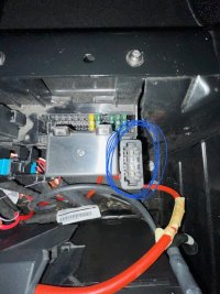
IS1 - Electrical interface for external use, terminal strip in driver’s underseat box, factory option, 70 euros.

Consists of three "plugs": gray, yellow, purple as in the picture.

View attachment 30775
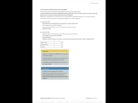
Full document at Body builder guidelines: Transporter - BodybuilderDatabase
Chapters:
2.5.2 Vehicle electrical system,​
2.5.3 Electrical interface for special vehicles​

Hi, does anyone know where I might find the actual pin out for the grey, yellow and purple connectors please? I have looked in the members area and found the 6.1 External Interface diagram but cannot find one for the 6. I have also read the builders guidelines but it seems to just refer to red and yellow/black positives in (maybe) one plug, but there are three. It also refers to erwin for the complete diagrams.

I have these plugs in my van and can see that there are many other wires coming in other than just red and yellow/black so I was hoping that there was a concise wiring diagram or pic out somewhere (For example I think there would be switched Live and switched negative for the doors so you can turn internal camping lights on etc)

Thanks in advance if anyone has it.
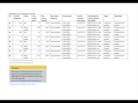
I'm not sure if I understood correctly. The Body builder guidelines (T6) chapter 2.5.3.3 has complete description of functions on all pins in all three plugs.
Unfortunately the courtesy circuit (switched live and switched negative for the doors) is not wired into the plugs.
A wiring diagram for the T6 interface has been available e.g. here in chapter 87 or 88.
 
Hi mm, I must be looking at a different version of the builders guide as all I see are the following pages regarding the connectors and 2.5.3.3

795A437B-2A5C-48BE-9CA1-98B7A8A5B31B.png

AC274A3E-FCAB-4623-A604-FADFD9E19755.png
 
Yep...just checked and the version I had did not have the pin outs for the connector blocks for some reason. All sorted now.

Cheers
 
  • Like
Reactions: mmi
Yep...just checked and the version I had did not have the pin outs for the connector blocks for some reason. All sorted now.

Cheers
That's good. The screenshots above are actually from a T6.1 document.
Just for future reference - nowadays T6 documents are found in the link under "Previous models".
 
Back
Top