Solar Power Monitor - CTEK250SA

RikParr73

Member
T6 Pro
Hi

I have a 120w solar panel running to my CTEK250-SA. I have just bought the Victron SmartShunt (Not installed yet) and would like to see what power I am getting from the solar panel. Not sure the shunt does that, so what would be the best kit to install to monitor solar output please along with the shunt? Thanks in advance.
 
The best thing would be to take the solar OF the Ctek.

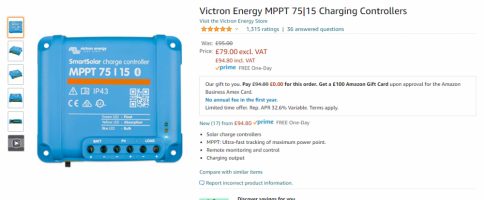
And fit a seperate Victron mppt solar conteoller... that has the full solar data logging.

Have a look at the 75/15.


FYI:

The shunt will show you the NET power going into or out of the battery bank.

so sunny day would be, solar - loads = shunt reading

the shunt will show you the ctek dc-dc charge.

the shunt will show you the loads draw - at night/engine off.
 
Last edited:
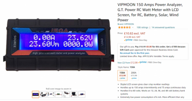
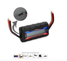
or if you want to it an inline power meter to your existing setup look at one of there . .


+++


1627824911657.png1627824932080.png
 
more info here:


and here:


+


**************************************************
Dellmassive`s -- "how I Done It" -- Thread
**************************************************
Kit List And Stuff -- How I Done It & What I Use --
**************************************************
VIP Membership | VW T6 Forum - The Dedicated VW Transporter T6 Forum
************************************************
For Sale - Summer-weekend-t6f Limited Edition External Stickers
For Sale - T6F Flags
**************************************************
 
The best thing would be to take the solar OF the Ctek.

And fit a seperate Victron mppt solar conteoller... that has the full solar data logging.

Have a look at the 75/15.


FYI:

The shunt will show you the NET power going into or out of the battery bank.

so sunny day would be, solar - loads = shunt reading

the shunt will show you the ctek dc-dc charge.

the shunt will show you the loads draw - at night/engine off.
Thanks for your reply. To be honest I was thinking the same, the CTEK is pretty useless for stats etc, I have the CTEK battery monitor and to be frank it's crap. Fitting the MPPT gives more flexibility (Wish I had done this initially before running the solar cables from the back end of the van to under the passenger seat - oh well lessons learned!) As you know from another post, I will be running a second solar panel, will the 75/15 accommodate this?
 
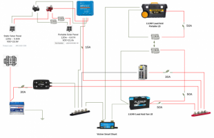
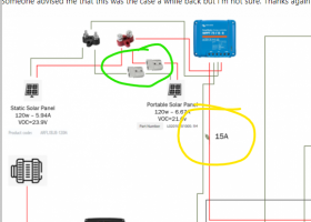
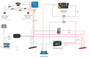
Ok, checked out your linked guides - very helpful!! Thanks. So I have updated me proposed new wiring diagram incorporating the MPPT 75/15 which is on it's way and due to arrive tomorrow. I am going to introduce a portable solar panel - decided on an ECO-Worthy 120w - £145.99 Amazon/ebay. Does the wiring look to be correct please and will the 2 panels be ok wired in parallel, this is where I'm struggling/unsure? Also, will I need to wire in a diode to prevent any issue should one of the panels become defective when both panels in use? Someone advised me that this was the case a while back but I'm not sure. Thanks again for your time, it's appreciated.

1627916392019.png
 
looks good . . .

the only thing i would do different:


+++

Green - i would use MC4 solar panel connectors and not Anderson.

Yellow - i would use 20A and slightly thicker cable. . . so when running at 15A the fuse doesn't get hot.

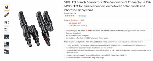
you could even swap out the RED/BLACK solar PV mini busbar for a set of PV branch connectors . . . - shown below.

+++

1627920448630.png


+++


i wouldn't bother with a blocking diode as this is a small install and the panels are in parallel (not high enough voltage to be a problem).


.

FYI

MC4 connectors kit.


1627920649752.png


++++


Solar branch connector.


1627920821355.png
 
Why is the Neg side of the portable battery going to the bus bar side of the shunt not the battery side? Only asking as I’m about to fit a shunt to my set up which is identical to yours
 
Why is the Neg side of the portable battery going to the bus bar side of the shunt not the battery side? Only asking as I’m about to fit a shunt to my set up which is identical to yours
It is going to the battery via the anderson connectors, well that's my theory Dellmassive may be able to shed some light on it though, just in case I am wrong lol.
 
Last edited:
looks good . . .

the only thing i would do different:


+++

Green - i would use MC4 solar panel connectors and not Anderson.

Yellow - i would use 20A and slightly thicker cable. . . so when running at 15A the fuse doesn't get hot.

you could even swap out the RED/BLACK solar PV mini busbar for a set of PV branch connectors . . . - shown below.

+++

View attachment 125919


+++


i wouldn't bother with a blocking diode as this is a small install and the panels are in parallel (not high enough voltage to be a problem).


.

FYI

MC4 connectors kit.


View attachment 125920


++++


Solar branch connector.


View attachment 125923
Great, thanks for the quick reply. I will go for the MC4, good idea. I will use 14 AWG (2.5mm2) cable for the 20A line that is currently 15A that you have suggested, that should be ok? What I'm unsure about is the cable size overall. I will use 2.5mm2 for all the 12v outputs, but for the heavy stuff, battery to battery/CTEK will use 16mm2, is that ok? Thanks.
 
It is going to the battery via the anderson connectors, well that's my theory Dellmassive may be able to shed some light on it though, just in case I am wrong lol.
Its tricky as the 2nd battery is removable...

The shunt needs setting to a fixed setup... ie 2xbatterys.. or 1xbattery.

So assuming the setup in programming for the shunt is for the 1xfixed battery . . . Eg 100ah....

Then adding the second battery will skew the readings..

So by tapping the 2nd battery off the 1st and bypassing the shunt will effect the readings..... untill the batterys are fully charged.... at which point the shunt will sync to 100%.

Ultimately... it could be done either way.

Doing it the other way will give the same skew in readings.... expecting 200ah of battery.... but only having 100ah (when second is disconected).

So best to go with the most likley setup for most of the time..... which id imagine would be one battery.
That’s what I’ll do Time to make a start…

A5B44A4A-6E10-489F-86BF-904451762D7D.jpeg
 
I'm running a 100 watt panel which is connected to my leisure batt through a controler
my question is i'm using a Nassa battery monitor and as all my earth cables go direct to the shunt should the solar earth also be going to the shunt or is it correct going to the Batt neg
 
I'm running a 100 watt panel which is connected to my leisure batt through a controler
my question is i'm using a Nassa battery monitor and as all my earth cables go direct to the shunt should the solar earth also be going to the shunt or is it correct going to the Batt neg
I'm no expert, but my panel neg goes direct to the controller, the battery neg from the controller goes to my bus bar which then goes to the shunt, then LB.
 
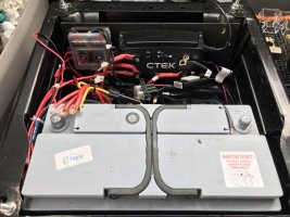
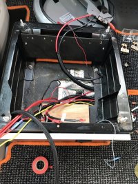
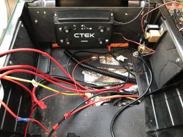
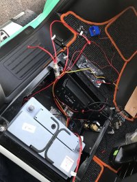
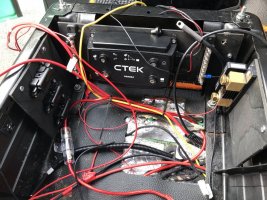
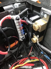
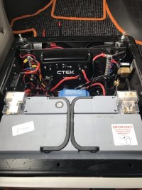
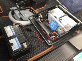
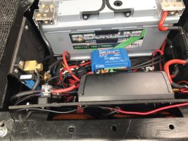
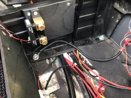
Ok, so I finished the job the day before we left for our 2 week holiday. Unfortunately I took out the EHU, Stereo and CTEK when I came to test everything. CTEK was easy fix 30amp fuse blown. Stereo, not sure so that's going back to audio place tomorrow. EHU they are looking at tomorrow also. I would have posted pics sooner but the day we got on hols the wife contracted COVID and since then it's gone through all the family apart from me. Anyway, here are some pics from start to finish that may (or may not) help you. Bit of a tight squeeze tbh, and could be a bit more tidy, but it'll do :)


1.JPEG2.JPEG3.JPEG4.JPEG5.JPEG6.JPEG7.JPEG8.JPEG9.JPEG10.JPEG11.JPEG12.JPEG13.JPEG14.JPEG15.JPEG16.JPEG


1630422993231.png
 
@Dellmassive - Hi, couple of things if I may? After taking the seat back out to have the stereo to leisure battery issue fixed I have since removed the leisure battery so I could replace some bolts for the seat. With the battery disconnected my Sargent EC155 started to alarm when starting the van and then switching off the ignition, I then discovered that there was still power to the sargent control panel/system. I assumed that there would be no power to the sargent as I had disconnected the LB. Upon checking I noticed, as per the wiring diagram above I was running the positive output from the ctek to the pos bus bar rather than the battery direct, so disconnected that cable, but still had power to sargent and other 12v devices. I then disconnected the neg cable from the solar panel to the MPPT and that finally cut power to all the sargent & connections running off the bus bar. So my questions are (based on above diagram) 1. Should the output from the CTEK go direct to the LB and not to the bus bar as shown? 2. Is it correct that the solar MPPT is powering the sargent/12v devices without any battery connected as nothing is connected to the MPPT load terminals and if so how is this happening? Thanks in advance. Rik
 
1- yes thats fine going to the busbar (you should remove the fuse from the starter battery feed to shut down the dc-dc and also disconnect the PV POS from the MPPT side - that will switch off all power going to the LB and make there disconnected terminals safe (its always good practice to fully insulate any disconnected terminals anyway))

2- the MPPT is putting out power on the BATTERY terminals. when the sun is out (Disconnect the PV POS to shut it down) - that power is connected to the POS Busbar so feeding power into the leisure side of the system. - thats why the sockets are powered up.

The LOAD terminals on the MPPT can be used as a lov voltage cut off - if the 12v for the lights and sockets etc were taken from that terminal.

but are subject to the max throughput of the mppt (thats 15A for a 75/15 mppt)

but you haven't got them connected that way so not relevent in your setup.


+++

there is also the possibility that the CTEK and Vic MPPT are detecting each others 12v output and assuming its the 12v from the LB 9which has been removed)

+++


so if future if you need to remove the LB from under the seat . .

remove the main fused feeding the DC-DC at the starter battery and disconnect the PV POS from the MPPT - that will shut down all charging power going to the LB


+++
 
Back
Top