You are using an out of date browser. It may not display this or other websites correctly.
You should upgrade or use an alternative browser.
You should upgrade or use an alternative browser.
Thanks @Robert - there are 2 live feeds and one earth into the 8 pin block so I tried each one in turnYou have to use one wire only.
But as described above you could wrap it for increased accuracy and then the reading has to be divided by number of wraps.
put the dc clamp meter round pins 3, 6 and 7 in turn
I am confused with your pin numbers?
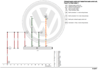
The 8 pin black connector has pin 4 at +12V (white wire coming into the connector block from the control unit), pin 3 as the 0V ground return (brown wire). Either of these individually should read several amps when the seats are on.
A green wire from the control unit goes to pin 2 of the 8 pin connector. This goes to the thermistor. This will only be milliamps.
This all assumes it is the same as the diagram I am looking at!
Ah - OK! I’m was looking at the wiring into J774 as I was trying to eliminate the relay as a problem. I figured that if there was no current going to the relay, then it definitely wouldn’t get to the smaller 8 pin (with pins 2,3 and 4 occupied that the elements plug in to)!I am confused with your pin numbers?
The 8 pin black connector has pin 4 at +12V (white wire coming into the connector block from the control unit), pin 3 as the 0V ground return (brown wire). Either of these individually should read several amps when the seats are on.
A green wire from the control unit goes to pin 2 of the 8 pin connector. This goes to the thermistor. This will only be milliamps.
This all assumes it is the same as the diagram I am looking at!
Started again with the same results
Ignition on, engine off:
Pin 3 (earth) of the Kufatec harness at 0.6 ohms
Pin 4 (live) of Kufatec harness at 12v
Ignition on, engine on, measured between pins 2 and 3
Switch on 3 (max) 14.07v
Switch on 2 (med) 14.07v
Switch on 1 (min) 14.07v
Switch off 0.06v
DC clamp meter on each individual element wire on:
pin 4 (12v+) 0.02a
pin 3 (0v) 0.02a
Started again with the same results
What is the resistance reading between pins 3 and 4 on the seat side with the seat disconnected from the van harness? (i.e. you are just measuring the resistance of the seat elements and not the control unit).
Pin 4 (live) of Kufatec harness at 12v
Is this voltage taken with the seat elements connected?
1.9 ohmsWhat is the resistance reading between pins 3 and 4 on the seat side with the seat disconnected from the van harness? (i.e. you are just measuring the resistance of the seat elements and not the control unit).
Pin 3 of T8 seat loom to ground bolt in dash is 0vAlso measure the voltage from pin 3 to a known good van ground point when the heated seat is switched on. This will check for a good ground return.
I am assuming the pin numbers are on connector T8.
NoIs this voltage taken with the seat elements connected?
You need to measure the pin 4 voltage with this supply under load; i.e. the seat elements connected. I think you will find it is not 12V !
Engine running, everything connected, seat switched on, measurements Pin to ground :You need to measure the pin 4 voltage with this supply under load; i.e. the seat elements connected. I think you will find it is not 12V !
Pin 4 voltage is 0
Pin 3 voltage is 0
Pin 2 voltage is 12v
Engine running, everything connected, seat switched off, measurements Pin to ground :
Pin 4 voltage is 0
Pin 3 voltage is 0
Pin 2 voltage is 0
Pin 4 voltage is 0
There is you problem. No voltage, no current.
Does your T8 pin 4 go to connection 5 (output) of the control unit? Not sure which loom you have.
You also need to check the +12V feeds to the control unit.
So should Pin 4 always have 12v - whether on or off?There is you problem. No voltage, no current.
Does your T8 pin 4 go to connection 5 (output) of the control unit? Not sure which loom you have.
You also need to check the +12V feeds to the control unit.
So should Pin 4 always have 12v - whether on or off?
Only when the heated seats are switched on.
Similar threads
- Replies
- 5
- Views
- 512
- Replies
- 2
- Views
- 658


