Planning electrics - location of all the parts - specifically inverters

Skyliner33

Senior Member
VCDS User
VIP Member
T6 Legend
I am now planning to redo all my electrics as I am looking to get a set of units, so this brings up several problems.

I had a look through this thread (and searched for others):

However I am struggling to find any answers.

Originally I hoped to put all the electrics under the 2 captains seats. However I want to install an inverter - this then causes me the problems.

My first thought was to just run a wire from the seat base to the back of the van for the inverter, but then I realised due to size of wire, current and therefore voltage drop this isnt a good idea.

Now I am struggling to think of where best to put everything.

This is proving had to imagine and plan, as I dont have units to look at and measure where everything can go.

I am therefore hoping that if you have a van with an inverter in your system you could let me know where everything has been fitted (any pictures to show the setup would be great).

(Edit - I forgot, there is an amplifier to fit under one of the seat bases as well :/)

Thanks in advance.

What I have already to fit:
Renogy 100Ah battery (possibly will add a second or get the Fogstar 230Ah one)
Victron bits (BMV712, dc-dc charger, mppt, smartshunt)
Busbars fuses etc.


Thanks
 
Last edited:
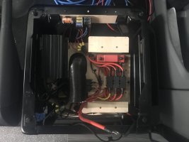
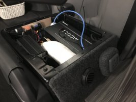
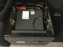
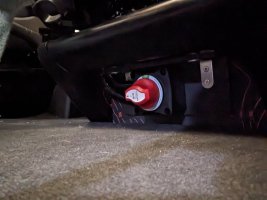
Under drivers seat. Renogy 1000W is about the limit size wise.
Had to raise it, so wiring, fuses and busbar all sit underneath; not ideal, but there just isn’t the space to have everything accessible.
I also had to extend my mains socket rearward to clear.

IMG_0874.jpegIMG_0891.jpegIMG_0890.jpegPXL_20231210_145906062.NIGHT.jpeg
 
Under drivers seat. Renogy 1000W is about the limit size wise.
Had to raise it, so wiring, fuses and busbar all sit underneath; not ideal, but there just isn’t the space to have everything accessible.
I also had to extend my mains socket rearward to clear.

View attachment 223100View attachment 223101View attachment 223102View attachment 223103
Thanks, I am hoping to get a 2kW inverter. Will have a look at size differences. Although I need to squeeze an amp in somewhere as well.
Where did all the OEM electrics that sere in the seat bases go?
 
Thanks, I am hoping to get a 2kW inverter. Will have a look at size differences. Although I need to squeeze an amp in somewhere as well.
Where did all the OEM electrics that sere in the seat bases go?
On the passenger seat base:
OEM wiring connector blocks were relocated to the inside front side of the passenger seat. I modified the OEM plastic mounting block, cutting off any excess bits and rearranged the connections to suit the factory wiring lengths, once they were all untangled.
OEM relays located to the rear inside side of the passenger seat, again reused bits of the original OEM mount.
OEM passenger seat fuse block scrapped completely and wiring / fuses rerouted over to drivers side.
OEM factory second battery fuse block scrapped.

On the drivers seat base:
OEM wiring connector block relocated to inside rear side of seat base; OEM rear plastic mounting block scrapped and connector block attached using 3M tape. OEM swivel wiring support on OEM rear plastic mounting block replaced by a straight bracket from the rear of the seat.

For the main earthing points on each seatbase I did the following

Thread 'Seat base stud bolt GND connection'
Seat base stud bolt GND connection

I removed both seat bases and the factory rubber matting, following the guides on here, so that I could see all the wiring, took off some of the loom tape and rerouted as I required. I also added some packing (using thin ply) between the van floor and the rubber in a few locations on the passenger seat to get a firmer more level base for the battery.

There was also enough of a void under the battery to put the excess length of cable from the Renogy battery monitor display and the Renogy remote inverter switch, to make the install neater.
 
Thanks, I am hoping to get a 2kW inverter. Will have a look at size differences. Although I need to squeeze an amp in somewhere as well.
Where did all the OEM electrics that sere in the seat bases go?
Are you absolutely sure you really need a 2kW inverter? That’s 166A on full beans. As I’ve said before, we have a 1600W inverter & hardly ever use it. You’re going to need some serious cable infrastructure to serve a 2kW unit. A 2kW unit is a huge lump!!
 
Thanks, I am hoping to get a 2kW inverter. Will have a look at size differences. Although I need to squeeze an amp in somewhere as well.
Where did all the OEM electrics that sere in the seat bases go?
If you are planning to use the 2kW you need to think about your batteries. Generally even a LiFePo will top out at 100A and that inverter will pull around 170A at full load.

So you would need at least 2 identical batteries that are warranted to work on parallel (not all LiFePo can due to BMS differences)

You are also going to need substantial cables so realistically you are looking at mounting both those batteries and the inverter very close to each other to deal with that current, so likely in the cabinets not the seat bases.

You should also consider how quickly you can replace that energy. 20 mins at 2kW is going to consume between 60-70aH (using an 80% efficiency) and a 30amp DC-DC or EHU charger is going to take 2 to 2.5 hours to put that back. You could move to something like the Renogy 50amp DC-DC but again that will need substantial cabling now over a distance to the cabinets.

You can do a usable 2kW setup, people around these parts have, but it's a substantial investment in hardware and space in the van to do it so be really sure you need that capability over a smaller single battery inverter system.
 
It would also be worth your while running some numbers in the 12 Volt Planet cable calculator if you are thinking of moving things a reasonable distance.

A 3m run for a 30amp DC-DC should be fine on 10mm2 so that's probably what you have in place as that's about the wire run to a seat base.

Moving the batteries to the rear will likely be closer to a 5m total run at which point all the cable should ideally be 16mm2 to avoid substantial voltage drop - so from the starter, to the charger then to the leisure.

This is likely why tucking electrics in the cabinets behind the drivers seat is popular as it keeps the high current wiring shorter.

As a thought a 100amp load should work with a 1m run of 10mm2 - so if your battery is in the driver's seat base and you can mount a 1kw inverter in the cabinet behind it that might be possible if you take care to keep the run as direct as possible.

Edited to note that while this works for voltage drop as @EAN points out below when you cross check with real world temp rises on cables it won't and I'd forgotten that when I moved from an illustration that there are other dimensions to consider when placing equipment to an actual concrete example.
 
Last edited:
  • Like
Reactions: EAN
Are you absolutely sure you really need a 2kW inverter? That’s 166A on full beans. As I’ve said before, we have a 1600W inverter & hardly ever use it. You’re going to need some serious cable infrastructure to serve a 2kW unit. A 2kW unit is a huge lump!!
I am thinking about putting in an induction hob and have the ability to take a microwave if wanted. Thats the reason.
 
If you are planning to use the 2kW you need to think about your batteries. Generally even a LiFePo will top out at 100A and that inverter will pull around 170A at full load.

So you would need at least 2 identical batteries that are warranted to work on parallel (not all LiFePo can due to BMS differences)

You are also going to need substantial cables so realistically you are looking at mounting both those batteries and the inverter very close to each other to deal with that current, so likely in the cabinets not the seat bases.

You should also consider how quickly you can replace that energy. 20 mins at 2kW is going to consume between 60-70aH (using an 80% efficiency) and a 30amp DC-DC or EHU charger is going to take 2 to 2.5 hours to put that back. You could move to something like the Renogy 50amp DC-DC but again that will need substantial cabling now over a distance to the cabinets.

You can do a usable 2kW setup, people around these parts have, but it's a substantial investment in hardware and space in the van to do it so be really sure you need that capability over a smaller single battery inverter system.
Hi, thanks for that. If I do got this way then I would probably go for the Roamer 230Ah battery, 250A continuous discharge and 3200W.
I would rarely, if ever, use 2kW for 20min. More than likely just a few mins to boil water for drinks.
It would also be worth your while running some numbers in the 12 Volt Planet cable calculator if you are thinking of moving things a reasonable distance.

A 3m run for a 30amp DC-DC should be fine on 10mm2 so that's probably what you have in place as that's about the wire run to a seat base.

Moving the batteries to the rear will likely be closer to a 5m total run at which point all the cable should ideally be 16mm2 to avoid substantial voltage drop - so from the starter, to the charger then to the leisure.

This is likely why tucking electrics in the cabinets behind the drivers seat is popular as it keeps the high current wiring shorter.

As a thought a 100amp load should work with a 1m run of 10mm2 - so if your battery is in the driver's seat base and you can mount a 1kw inverter in the cabinet behind it that might be possible if you take care to keep the run as direct as possible.
Thanks again, I am thinking about paying the Roamer fee where they work out all the kit needed and the wire sizes, then if you order kit from them they knock the fee off.

Food for thought, thanks again.
 
On the passenger seat base:
OEM wiring connector blocks were relocated to the inside front side of the passenger seat. I modified the OEM plastic mounting block, cutting off any excess bits and rearranged the connections to suit the factory wiring lengths, once they were all untangled.
OEM relays located to the rear inside side of the passenger seat, again reused bits of the original OEM mount.
OEM passenger seat fuse block scrapped completely and wiring / fuses rerouted over to drivers side.
OEM factory second battery fuse block scrapped.

On the drivers seat base:
OEM wiring connector block relocated to inside rear side of seat base; OEM rear plastic mounting block scrapped and connector block attached using 3M tape. OEM swivel wiring support on OEM rear plastic mounting block replaced by a straight bracket from the rear of the seat.

For the main earthing points on each seatbase I did the following

Thread 'Seat base stud bolt GND connection'
Seat base stud bolt GND connection

I removed both seat bases and the factory rubber matting, following the guides on here, so that I could see all the wiring, took off some of the loom tape and rerouted as I required. I also added some packing (using thin ply) between the van floor and the rubber in a few locations on the passenger seat to get a firmer more level base for the battery.

There was also enough of a void under the battery to put the excess length of cable from the Renogy battery monitor display and the Renogy remote inverter switch, to make the install neater.
Thanks :thumbsup::thumbsup:
 
  • Like
Reactions: EAN
Hi, thanks for that. If I do got this way then I would probably go for the Roamer 230Ah battery, 250A continuous discharge and 3200W.
I would rarely, if ever, use 2kW for 20min. More than likely just a few mins to boil water for drinks.

Thanks again, I am thinking about paying the Roamer fee where they work out all the kit needed and the wire sizes, then if you order kit from them they knock the fee off.

Food for thought, thanks again.
If you do that make sure it covers the cable run both sides of the DC-DC as well - which I assume is existing non Renogy kit - as that may have to change depending where you put the battery.

I'm quite a fan of an induction based system as you save the space of a gas system. If you can get one with variable power then running a hob for a bit longer at lower wattage to boil a kettle is likely to be kinder on the batteries if you have the option.

If you are thinking of using the UPS pass through to run the same electrics.of EHU and Inverter there are some grounding complexities to think of.

Be interesting to see what you settle on :thumbsup:
 
@Skyliner33 I boil water just fine with my 1000W inverter.

I’d be a bit careful with the quoted current ratings of cables: They tend to quote maximums which involve excessive heat.
I always like to use this handy graph which can be used to really understand the effects of temperature rise above ambient vs current and derate my cables accordingly.


For example a 10mm2 cable is quoted as 70A by 12v planet who use the manufacturers figures.
That is equivalent to 8awg; look at the table and you can plot that the temperature rise is going to be of the order of 45C above ambient. Assume an ambient temperature of 25C and your cable is sitting at 70C. No thanks.

I like to keep cables much cooler than that.

For example

I use 16mm2 cable (110A), 6awg, for my 40A dc dc feed

I use 35mm2 (240A), 2awg, for my 1000W inverter; at approx 100A.

Temperature rise above ambient is negligible.
 
Last edited:
If you do that make sure it covers the cable run both sides of the DC-DC as well - which I assume is existing non Renogy kit - as that may have to change depending where you put the battery.

I'm quite a fan of an induction based system as you save the space of a gas system. If you can get one with variable power then running a hob for a bit longer at lower wattage to boil a kettle is likely to be kinder on the batteries if you have the option.

If you are thinking of using the UPS pass through to run the same electrics.of EHU and Inverter there are some grounding complexities to think of.

Be interesting to see what you settle on :thumbsup:
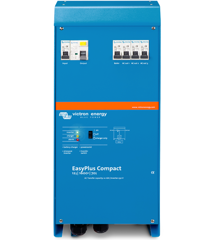
Yes, I have been looking at the Victron Easyplus. I contains the inverter, and handles the shore power side, all in one unit.

 
  • Like
Reactions: CAB
It would also be worth your while running some numbers in the 12 Volt Planet cable calculator if you are thinking of moving things a reasonable distance.

A 3m run for a 30amp DC-DC should be fine on 10mm2 so that's probably what you have in place as that's about the wire run to a seat base.

Moving the batteries to the rear will likely be closer to a 5m total run at which point all the cable should ideally be 16mm2 to avoid substantial voltage drop - so from the starter, to the charger then to the leisure.

This is likely why tucking electrics in the cabinets behind the drivers seat is popular as it keeps the high current wiring shorter.

As a thought a 100amp load should work with a 1m run of 10mm2 - so if your battery is in the driver's seat base and you can mount a 1kw inverter in the cabinet behind it that might be possible if you take care to keep the run as direct as possible.

@roadtripper 100A is way beyond the spec of 10mm2. I expect you’ve made a typo.
 
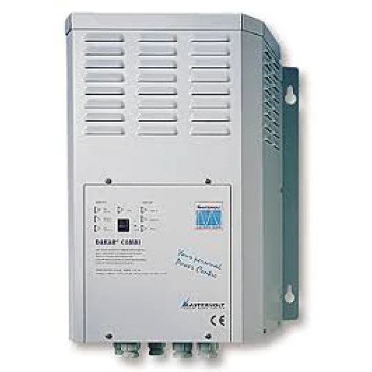
We have a Mastervolt Dakar combi (an older version of the all in one charger/inverter/changeover switch) as the heart of our narrow boat electrics and it's been brilliant for the last 20 years and is absolutely a no brainer in operation, all you need to do is keep an eye on battery SoC.

dakarcombi-768x768.webp


If you have the space to fit a similar system and are regularly going on and off EHU it's a good solution.
 
@roadtripper 100A is way beyond the spec of 10mm2. I expect you’ve made a typo.
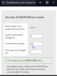
For 1m runs 12 Volt Planet has it within tolerance for voltage drop, though I take the point that @EAN raises that you need to consider cable temperatures as part of the choice too.

Screenshot_20231221-144436-01.jpeg

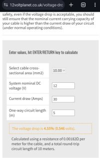
For voltage drop calculations remember the length is critical as well as the cross section. Hence why you get very different results for 1m (the 100amp calculation) and the 5m (the 30amp calculation)

Screenshot_20231221-145028-01.jpeg
 
@roadtripper
To quote the calculator you’ve used, it does say “you should still ensure that the nominal current carrying capacity of your cable is higher than the current draw of your circuit (under normal operating conditions)”
Decent spec OceanFlex 10mm2 cable is rated to 70A.
 
@roadtripper
To quote the calculator you’ve used, it does say “you should still ensure that the nominal current carrying capacity of your cable is higher than the current draw of your circuit (under normal operating conditions)”
Decent spec OceanFlex 10mm2 cable is rated to 70A.
considering the possibility that the cables would be run under insulation, I'd be running them in flexible conduit & massively over speccing size wise if it was my job. The thoughts of hundreds of amps flowing around the van frankly scares the bejeesus out of me. Possibly because I'm an electrical engineer (retired) & I've seen what electrickery can do in the wild.
 
  • Like
Reactions: EAN
considering the possibility that the cables would be run under insulation, I'd be running them in flexible conduit & massively over speccing size wise if it was my job. The thoughts of hundreds of amps flowing around the van frankly scares the bejeesus out of me. Possibly because I'm an electrical engineer (retired) & I've seen what electrickery can do in the wild.
I’m a retired aerospace design engineer and because of my background I’m also overly cautious.
I’ve also grounded (as in prohibited from use) equipment where my professional opinion was sought and I found incorrectly specified or fitted wires, circuit breakers etc..
 
Back
Top