Faulty solar panel or MPPT controller?

WillWillWill

Farmer
VIP Member
T6 Pro
Hi everyone, long term lurker, first time poster. Hoping that someone might be able to help me out with a problem please.

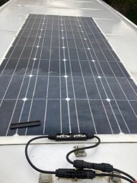
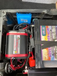
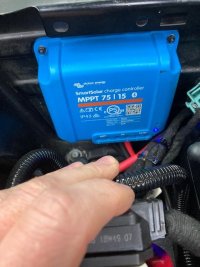
I have an issue with the solar charging on my van. This has been working fine and is not a new install. The important parts are a flexible solar panel (YH-150) connected to a Victron 75/15 MPPT controller.

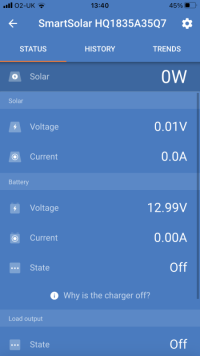
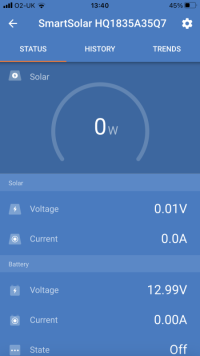
When I connected to the controller this morning via the Bluetooth app it forced a fw update to v1.59. I am not sure what it was on before, but I probably haven't connected to it for 6 months or so. Update went fine but ever since, the controller is registering 0V and 0A from the panel. The leisure battery is fine and registers ok.

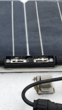
I have put my meter across the panel outputs directly (with and without anything further along connected including the load) and get 0V and 0A here too. This to me suggests the panel is completely stuffed, but before ordering a new one I wanted to make sure I wasn't missing anything stupid (like the internal resistance of the panel being so high I wouldn't get a reading or something).

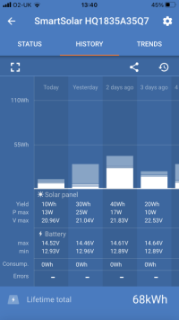
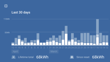
Under any other circumstance I would just get a new panel, but that it happened right after the firmware update is a coincidence to end all coincidences. My history in Victron shows some level of charging right up until today.

Panel is in the sun, clean, checked the continuity of the leads, no obvious corrosion, fuses ok, cable resistance within expectations, rebooted the controller. That's all I can think of.

Thanks for any help and advice offered.
IMG_5921.PNGIMG_5922.PNGIMG_5923.PNG

IMG_5924.PNG
 
Are you sure there is 0 volts at the terminals coming from the panel ?
 
As far as I can tell, yes. I started in the MC4s, but then opened up the junction box on top and went as close as I could to the terminals coming out of the panel itself (trying to bypass any possible corrosion). I find it almost unbelievable to get 0V, 0A but I have checked and checked again. Also made sure the meter wasn't faulty.....
 
have you got a few pics of the MPPT controller wire connectors . . ?
 
I had problems recently with a new Allpowers 100W foldable solar panel, where I couldn't get any power to the end user. With a bit of help from You Tube I resolved the issue. The MC4 connectors were wired up incorrectly. This maybe a long shot but maybe worth a try.
 
but . . .

if you saying the sun is out . . and you are getting 0V from the panel,

then the panel is faulty, or you have a corroded wire from the panel to the controller?
 
Thanks for the help and suggestions.
Here are some more pictures:

Tested the voltage inside the junction box at the back of the solar panel here with 0V, 0A shown, with and without the MC4s connected.
thumbnail_IMG_5928.jpg

Then unfortunately my MPPT is attached with tiny bolts under the seat, so a totally unsatisfactory photo of what you are after. However I did take this all out this morning and checked the terminals. The ends of the cables have got bootlace ferrules crimped on them which are fully seated and screwed down. I also checked the resistance of the cable between here and the roof MC4s and this was fine.

thumbnail_IMG_5929.jpgthumbnail_IMG_5930.jpg

Having absolutely no output from the panel has me very confused - I have never seen it before. It drops off or whatever but not total failure from a working state a few minutes before. But I don't have that much experience with them so maybe I just got unlucky.

Really appreciate the help. If it is a failure I'll just have to get a new one. I read through the recommendations and unfortunately the Photonic Universe one is out of stock, but looks like some of the Renogy ones are available.
 
No voltage from the panel.....

Means the panel is knackered.

I think you might need a second panel to test.....

Have you a mobile panel?...


Or access to another panel temporary?
 
Are you testing the panel open circuit? ie the wires (MC4 connectors) are disconnected and hanging loose? I too find it strange that an update should cause damage (if that's what has happened)
Can you test continuity of the cables from panel to MPPT? Using OHMS setting, test from panel to far end of each wire to check there's a connection.
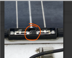
Is there a couple of diodes in the panel connection box?
 
@Dellmassive unfortunately no I don’t have a second panel or know of anyone with one to test. I am inclined to agree it is stuffed and needs replacing.

@Grim Reaper I have tried both OC and with the load connected. I also tried a different load as well. I have checked the cable resistance and including the 5m test lead it registered as about .2 ohms. There is indeed at least one diode in the junction box, but even probing before these, right as close to the solar tags as I can get still shows no output.
 
Do you know how to test the diode? It may have gone short circuit and be shorting the panel output out so you won't get any readings out of it.
 
I think so - few hundred ohms one way, extremely high resistance the other. My multimeter might even have a diode checker - I'll look tomorrow. Not sure what type of diode it is though and what it is even for in a solar panel..... I know a little about blocking and bypass diodes but this is not one of them, is it? It looks to be between the outputs so is more in a rectification setup than anything else?

No idea what type it is though or if the anode and cathode are identifiable in its current position. I'll look in the light tomorrow, but I guess as long as it works one way around it's good, if it is the same both ways, probably needs a new one. If that is possible without junking the whole thing.

Edited to add a better picture. Positive lead is on the right.

35AA0F1F-AD35-49E6-9A3A-9FCE3A8809E2.png
 
Last edited:
that looks like a 15A Smart Bypass Diode to me . . .


1649794361969.png1649794371840.png


++++++++++


so if you have no voltage from the panel in daylights . .


either the bypass diode has gone short circuit,

or,

there is a break in the track on the panel.

or

corrosion in the terminal junction box.


.


1649794574838.png

.
 
It sounds like the panel is knackered (really knackered, when I broke one I still got some output).
Long shot but maybe you live near a forum member with a portable panel to test.
 
I'm guessing there's a third foil strip from the panel beneath that black component
junctionbox.jpg diodes.jpgSolarWiring3.jpg

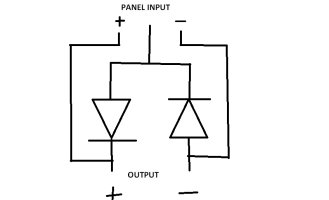
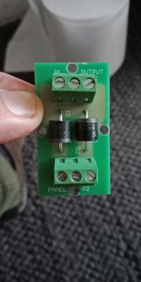
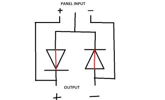
My panel has a rear exit so the diodes are in a separate box (ignore the screenprinting on the PCB, it is the wrong way around as I found out when it didn't work when I connected it up) The 3 wires from the panel comes in at the top and outputs at the bottom as per the diagram.
 
If the diodes have gone faulty and are short circuit both ways, then the solar panel is shorted across the output so you won't see any voltage across the panel output at the bottom.
diodefaulty.jpg
 
I don't know if having a permanent short across the panel in sunlight will have a detrimental effect on it, but I suspect it will. It might be a good idea to cover the panel until you can work out what's going on.
 
Once again, thanks to everyone giving up their time to help with this. I have had another look this morning.

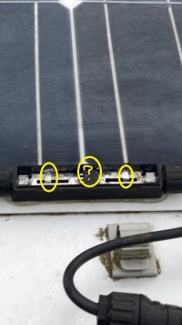
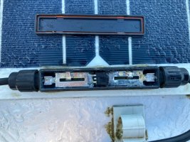
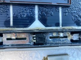
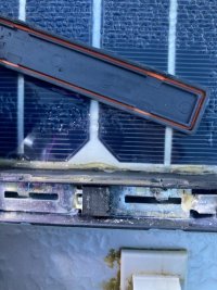
Here is the junction box, positive term on the right:
thumbnail_IMG_5937.jpgthumbnail_IMG_5938.jpg

I managed to get the lighting correct to identify a part number and circuit diagram on the diode.
thumbnail_IMG_5941.jpg
Googling for 20S0045 doesn't bring up a lot, except a post from someone with a similar issue and line of investigation but the diagram suggests it is a couple of blocking diodes from the outside pins to the center tag.

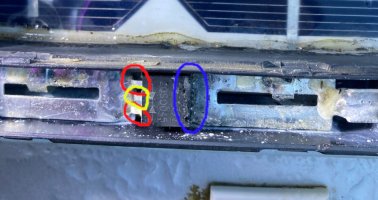
Here I get confused - both outside pins (red) are connected to the same solder plate in the junction box and the center pin (yellow) looks to not be connected.
thumbnail_IMG_5941m.jpg
However there is copious amounts of solder/bonding between the top of the component (blue) and the tag on the right as well, so maybe there is something going on under the diode that I cannot see. I have tried to dig around as best I can, but there is so much solder everywhere, it is all pretty much immovable and I am going to have to wreck it to get it out.

I then tested the forward bias of the diode and with the red probe on either of the outside pins and the black one on the center I either get .7 M Ohms, or continuity with the diode checker. With the probes reversed I get over limit/no continuity, which to me looks correct.

With the panel open circuit (loads disconnected) I get continuity between the neg and positive sides when the red probe is on the negative, but not the other way around. I need to think about the implications of that one a bit more.

Sorry if this is getting a bit involved when the easiest answer is to chuck it away and get a new one. I just like to understand why stuff is broken if I can.
 
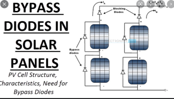
that looks to me like they are just using that as a blocking / bypass diode.

with both halves in parrallel to increase the current capacity.

your two red pins are in parallel,

yellow has no connection,

so you have a twin diode over to your blue connection.


+++++

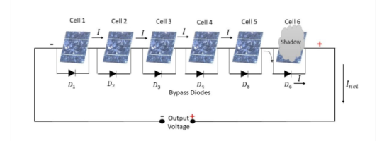
so that will act as a bypass diode for panels in series.

(but if it had failed and gone short circuit, it would effectively short out the panel + & - tabs giving a dead short panel, which will just get hot in sunlight and effectily 0v reading at the panel output)


++++++


1649842244549.png


...


1649842346005.png
 
Thanks that is now beginning to make a bit more sense to me - in my setup, the diodes don't do a lot because there is only one panel, but are there for the potential series setup. Then as you and Grim have explained, if the diode fails and shorts it is causing the problem I see.

The diodes tested out ok this morning, and now I have just gone back out and found that I am once again seeing output from the panel at the controller. After bashing my head repeatedly into the solar panel I calmed down and checked and sure enough also see output at the panel itself.

So either the diode needed a good night's sleep and is now back on form today, or it is temperamental/on the way out. Maybe current or temperature related? I am clutching at straws.....

I'll monitor it through the day and see what happens. I'll at least have a better idea now because if I stop seeing panel output, hopefully I will also find it fails the diode test, since currently everything is ok and the diodes are working.

Not sure whether I could successfully get that out of there without wrecking the box because I think they used pigeons to apply the solder. But nothing to lose so I'll try and find a similar component to fit if I do need.
 
Back
Top