looks like the Stirling are using Prismatic cells . .
 sterling-power.com
the sheet detail BMS functions.
-20degc discharge cutoff - but not the charging temp
10v - low voltage disconnect.
high/low - voltage


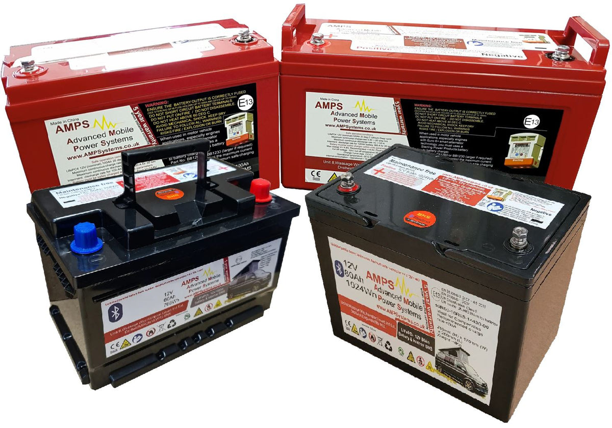
Lithium Batteries 12V Leisure Battery (5 Year Warranty)
AL series LiFePO4 - Lithium Iron Phosphate batteries. Spec list Charge Discharge Part No Ah Capacity Charge V Current (A) (max) Current (A) (max) Bluetooth heater Series limit Dimensions (cm) LWH Weight (Kg) Battery Terminal AL1220 20Ah <14.4V 20A 40A no no 48V 19 x 7.7 x 18.7 2 M5 5mm AL1260...
sterling-power.com
the sheet detail BMS functions.
-20degc discharge cutoff - but not the charging temp
10v - low voltage disconnect.
high/low - voltage


")
