You are using an out of date browser. It may not display this or other websites correctly.
You should upgrade or use an alternative browser.
You should upgrade or use an alternative browser.
Dash Switch Wiring
- Thread starter Sydney2london
- Start date
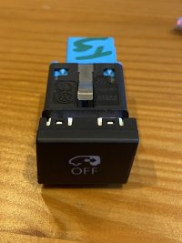
Wires are 000 979 009E
Housing is 8W0 971 636D (nose perhaps needs a little cut-off, but then fits perfect to all switches at all positions)
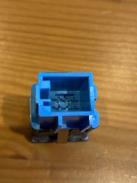
Wiring diagram is
Pin 1 GND Status-LED (yellow)
Pin 2 +12V for Status-LED (yellow)
Pin 3 +12V for Orientation-LED (red)
Pin 4 in (switch)
Pin 5 out (switch)
Pin 6 GND for Orientation-LED (red)
-> seen from the back of the button
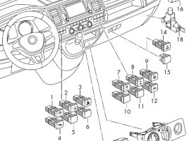
All „switches“ in your dashboard (double-six-block left and right) are buttons (not really switches). So if you need a permanent-on function you need a flipflop-relay
Here‘s a picture of the connector… don‘t buy the cables at the local VW dealer… far too expensive. Can be found at ebay or anywhere else in the www for a much cheaper price.
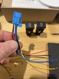
This is what I do with the switches
(down right)
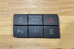
Switching my parking heater on/off and showing status (yellow when running)
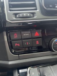
Housing is 8W0 971 636D (nose perhaps needs a little cut-off, but then fits perfect to all switches at all positions)
Wiring diagram is
Pin 1 GND Status-LED (yellow)
Pin 2 +12V for Status-LED (yellow)
Pin 3 +12V for Orientation-LED (red)
Pin 4 in (switch)
Pin 5 out (switch)
Pin 6 GND for Orientation-LED (red)
-> seen from the back of the button
All „switches“ in your dashboard (double-six-block left and right) are buttons (not really switches). So if you need a permanent-on function you need a flipflop-relay
Here‘s a picture of the connector… don‘t buy the cables at the local VW dealer… far too expensive. Can be found at ebay or anywhere else in the www for a much cheaper price.

This is what I do with the switches
(down right)

Switching my parking heater on/off and showing status (yellow when running)

If you join as a VIP member there are also pretty extensive wiring diagrams in the download section that you may find useful.
If things are using the OEM stock wiring for the lights you'll need more than just a switch. The arrangement is that the power supply +12v for the lights comes via the BCM and is on a failsafe time out (generally 20mins, 60mins for some vans with LED cargo lights, can be coded up to 127mins) The lights then have 2 grounds, one via the door switch (so they come on when door open) and permanent (so you can switch them on)
Upshot is unless you switch in a source of power from elsewhere the most you'll get is about 2 hours. There are quite a few threads around the forum using a changeover switch to either use the normal BCM feed for everyday driving or a permanent live when camping, usually from the leisure battery to protect the starter.
OEM stock power is usually permanently live, the difference is if you have second battery most of them come off that (apart from the one by the gear leaver which remains the starter)
So you perhaps have one of the Sargent style all in one 240v/12v PDU systems that kill the power when the engine is running for EMC compliance? Some of those use the same signal to switch other things like fridge and split charge relays so double check there. A lot of folks add a small auxiliary fuse box directly off the battery and move the loads they want on 24/7 there.
Amazing, thank you so much! The advise on the relay is great. Btw, do you access these by removing the fascia around the screen? Thanks!Wires are 000 979 009E
Housing is 8W0 971 636D (nose perhaps needs a little cut-off, but then fits perfect to all switches at all positions)
Wiring diagram is
Pin 1 GND Status-LED (yellow)
Pin 2 +12V for Status-LED (yellow)
Pin 3 +12V for Orientation-LED (red)
Pin 4 in (switch)
Pin 5 out (switch)
Pin 6 GND for Orientation-LED (red)
-> seen from the back of the button
All „switches“ in your dashboard (double-six-block left and right) are buttons (not really switches). So if you need a permanent-on function you need a flipflop-relay
Here‘s a picture of the connector… don‘t buy the cables at the local VW dealer… far too expensive. Can be found at ebay or anywhere else in the www for a much cheaper price.
View attachment 221048
This is what I do with the switches
(down right)
View attachment 221049
Switching my parking heater on/off and showing status (yellow when running)
View attachment 221054
The best way to access these is actually removing the fascia around the radio.
Some say it works also by trying to clip the buttons off with a plastic trim tool but I wouldn‘t go for the risk of having scratches or other damages in the plastic surface.
Once having the fascia removed you can easily push the buttons out by moving them a little bit up and down. Just be patient. No problem at all.
Hey, could you please help me with the numbering?Amazing, thank you so much! The advise on the relay is great. Btw, do you access these by removing the fascia around the screen? Thanks!
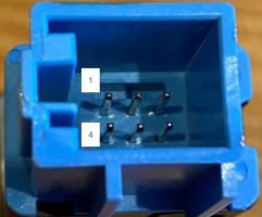
Is this pin count correct? It's the back of the button.
Also, where did you get the connector and wires in this photo?
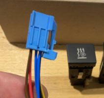
I found some on ebay but not like yours.
Thanks a mil!
Last edited:
Thanks, found it! Sorry, I was looking for the code with the spacesGenerally if you google the part number of a connector housing there’s often ebay (or similar) sellers that do aftermarket plugs populated with flyleads
Could I ask one more favour please? Could you please confirm if this pinout of the button is correct?
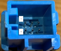
Thank you so much and have a lovely evening!
Thanks, I only need the bypass for the ignition when I'm driving, so I can power the red led using the ignition line through the relay so it's either red when normal or yellow when switched. Should work, will post and update!If you join as a VIP member there are also pretty extensive wiring diagrams in the download section that you may find useful.
If things are using the OEM stock wiring for the lights you'll need more than just a switch. The arrangement is that the power supply +12v for the lights comes via the BCM and is on a failsafe time out (generally 20mins, 60mins for some vans with LED cargo lights, can be coded up to 127mins) The lights then have 2 grounds, one via the door switch (so they come on when door open) and permanent (so you can switch them on)
Upshot is unless you switch in a source of power from elsewhere the most you'll get is about 2 hours. There are quite a few threads around the forum using a changeover switch to either use the normal BCM feed for everyday driving or a permanent live when camping, usually from the leisure battery to protect the starter.
OEM stock power is usually permanently live, the difference is if you have second battery most of them come off that (apart from the one by the gear leaver which remains the starter)
So you perhaps have one of the Sargent style all in one 240v/12v PDU systems that kill the power when the engine is running for EMC compliance? Some of those use the same signal to switch other things like fridge and split charge relays so double check there. A lot of folks add a small auxiliary fuse box directly off the battery and move the loads they want on 24/7 there.
Your pin count is correct.Hey, could you please help me with the numbering?
Is this pin count correct? It's the back of the button.
View attachment 221388
the connector housing in my above picture is the original VW part nr. 8W0 971 636D,Also, where did you get the connector and wires in this photo?
the cables are aftermarket (bought at ebay for like 4€ per 10pcs.)
Thank you so much!Your pin count is correct.
the connector housing in my above picture is the original VW part nr. 8W0 971 636D,
the cables are aftermarket (bought at ebay for like 4€ per 10pcs.)
Ok got it all working on the bench, thank you so much for your help!! Can I pick your brain one more time plz?…wrote at the same time
I plant to have the button with the relay behind it, and have two wires running from the fuse box: a live (from ignition) and a ground, and one running to the back of the van (the ignition signal from the relay).
Do you know if I can get power and ground from one of the other buttons on the dash without the need to wire them from the fuse box?
Thanks a mil!
You can take the ground from any other of the switches next to your new switch, it is always the same pinout. Not sure if there is a live power (not on ignition) on the others, but I suppose the warning lights switch has one. To be sure I guess you probably should check the cable plans ore measure it out.
ok I think I’m better off running ignition from the fuse box on a 1a fuse or something and then powering everything from there. Can I just splice into the ground of a nearby button or is there a better place in the area to get ground? ThanksEdit: make sure you do not use the power from the switch next to yours for load (only for trigger) at your relay…
If you already have a ground wired from behind the fuse box (as you said in #13) there is no need for any other ground…
I think it is then:
- ground for the relay (trigger - ) AND the LEDs in the switch
- live power either from a neighbor switch or from your new wire from the fuse box to the „in“ of your switch and then from your „out“ to the trigger in of your relay (trigger + )
- positive with „lights on“ for the red LED (orientation LED) from a neighbor switch
- power with ignition from the fuse box to the „common“ pin on your relay (load)
- switched load (your positive) from the relay (it is the „nc“ pin, „normally closed“) to the back of the van AND to the positive of the yellow LED of your switch (status LED)
Maybe this reads more complicated than it actually is. It all comes with doing it…
Hey! Just wanted to say thanks, got it working. I wired all the lives to the ignition so the red led is always on (will fix that at some point) but otherwise it works perfectly.If you already have a ground wired from behind the fuse box (as you said in #13) there is no need for any other ground…
I think it is then:
- ground for the relay (trigger - ) AND the LEDs in the switch
- live power either from a neighbor switch or from your new wire from the fuse box to the „in“ of your switch and then from your „out“ to the trigger in of your relay (trigger + )
- positive with „lights on“ for the red LED (orientation LED) from a neighbor switch
- power with ignition from the fuse box to the „common“ pin on your relay (load)
- switched load (your positive) from the relay (it is the „nc“ pin, „normally closed“) to the back of the van AND to the positive of the yellow LED of your switch (status LED)
Maybe this reads more complicated than it actually is. It all comes with doing it…
Thank you so much for your help!!
Where did you get this Button ? I dont find it in ETKA, and how did you wire it ? I changend my Aux, Heater to work with the original VW key and with the Roof Display. But i would like to have this fancy Button as well.Wires are 000 979 009E
Housing is 8W0 971 636D (nose perhaps needs a little cut-off, but then fits perfect to all switches at all positions)
Wiring diagram is
Pin 1 GND Status-LED (yellow)
Pin 2 +12V for Status-LED (yellow)
Pin 3 +12V for Orientation-LED (red)
Pin 4 in (switch)
Pin 5 out (switch)
Pin 6 GND for Orientation-LED (red)
-> seen from the back of the button
All „switches“ in your dashboard (double-six-block left and right) are buttons (not really switches). So if you need a permanent-on function you need a flipflop-relay
Here‘s a picture of the connector… don‘t buy the cables at the local VW dealer… far too expensive. Can be found at ebay or anywhere else in the www for a much cheaper price.
View attachment 221048
This is what I do with the switches
(down right)
View attachment 221049
Switching my parking heater on/off and showing status (yellow when running)
View attachment 221054
Thanks in Advance!
Similar threads
- Replies
- 10
- Views
- 1K
- Replies
- 11
- Views
- 940
- Replies
- 2
- Views
- 665
- Replies
- 1
- Views
- 634

