British summer-Need an EcoFlow

Samro

Senior Member
VIP Member
T6 Legend
Stuck in Britain with no T6 yet (as it approaches 12 months from placing my vehicle order) but who cares, I’ve been using my time wisely and planned my conversion in such minute detail that it’s going to be awesome!

Now that the schools have broken up, we’re away as a family (of five) in our caravan and because this is the first extended holiday (that we’ve only just started) spent “off grid” in Britain, it has come as a bit of a revelation that that my 550W of solar panels and 240Ah of batteries are absolutely pants at running everything that we’re used to in the south of France!

Okay, don’t get me wrong, most families would be ok with what is quite a capable system, but my family seem determined to take the p*$$! Four coffees from the Nespresso and I get told “The toaster is broken!”

These last few days have been ok and we can occasionally use a coffee machine, vacuum the grassy floor, etc, but the single issue for me is the extra fridge….. after being overexposed to my own family for a full day without the normal respite provided by going to work, an extra fridge dedicated to beer and wine is more important that I could have ever imagined!

So, 4 days of insufficient sun led me to refer to this mighty forum and BOOM! The problem is resolved which is is largely down to @Dellmassive threads relating to Ecoflow and Allpowers products!

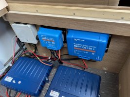
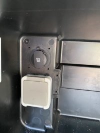
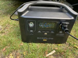
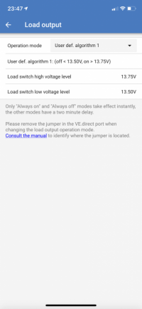
I installed a new cigarette socket rated at (20A) and fed it from the smaller of my MPPT controllers load ports. (Now, when my solar has a system voltage to over 13.75V (for 2 mins) the Ecoflow Pro takes a charge of 8A. (I could reduce this if I need to.)
If system voltage falls below 13.5V (for 2 mins) the Ecoflow stops being charged.
1627426134726.png

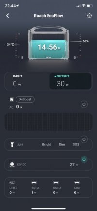
I set this up this morning and on a pretty cloudy day (sigh) and achieved fully charged domestics and Ecoflow. The fridge now is plugged in to the Ecoflow and at 11pm, the Ecoflow app tells me i have nearly 15 hours until daylight will recover my situation.
1627426012661.jpeg

I have a slight issue in that the shunt does not recognise the power being taken from the load ports of the mppt. I can live with this for the odd times I am going to need cold beer and wine when there is little sun, unless anyone on here can tell me a way of accounting for thud better? (I have a Venus GX but both relays are doing other things, so can’t use this.)
 
glad you found the threads informative . .

something is not right with your shunt wiring if you are not reading the MPPT load current. (make sure all grounds are to chassis and ONLY the shunt is connected to the battery bank NEG post.)

you should be, . . . and mine does.

example below . .

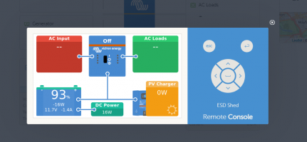
-15w being drawn from the battery via the MPPT load output - that running LED lighting in garden.

make sure you have "DC System" switched on settings and that all units are FW uptodate.

also are you using the VE-Local network feature? - is it set correct?

any pics of your system for us to see?


1627471032891.png

.


1627471053509.png
 
Thanks.

I had made an assumption that the consumption from the “Load” on the MPPT controller would not be accounted for by the shunt as all negatives should be connected to the load side of the shunt. From your comments I assume that any consumption from the “load” ports on the mppt are communicated to the gateway via the VE network?


Incidentally, turning on “has DC system” has disastrous results with the consumption figures in Remote Console when using a Phoenix inverter With VE networking. It works fine, but the consimption from the inverter is accounted for twice and displayed incorrectly on the console where your screenshot shows “AC Loads”. The console shows the loads, but also shows the load on the DC side so the total load is doubled!
Victron have simply fobbed me off on this issue and told me to either turn off “has dc system” or remove the inverter from the VE network.
I couldn’t live without the AC consumption being displayed correctly so turned off the functionality.

Here are a few pics:
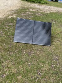
Renogy 200w mobile panel.
1627489463450.jpeg
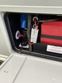
Remote panel connects to van via Anderson connector in battery box.
1627489664274.jpeg
2x 175W Victron panels on the roof use the bigger of the two MPPT controllers. The smaller of the two has the load output.
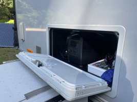
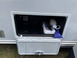
1627489756808.jpegLoad output is taken to an external locker where I’ve mounted the cigarette socket.
1627489825632.jpeg


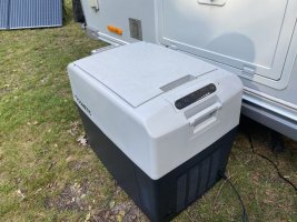
The Ecoflow neatly stores in this locker.
1627490052117.jpeg
1627490091316.jpeg
1627490113012.jpeg

1627489925279.jpeg
 
nice setup . .

got a couple of pics of the Shunt and battery NEGS?


FWIW . . .

The MPPT Load output is derived from the battery terminals . . . which inter are connected to the battery . .

so with no solar . . . . the battery will supply the load output, which is pulled from the battery . .


which should be monitored via the shunt . .


that will change if you have solar power coming in as it will offset the pull on the battery. . .
 
I am confident that there are no issues with where connections have been made. (I am also confident it needs a tidy up!)

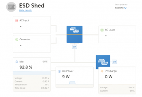
After looking at the VRM and Remote Console today, I can confirm that the shunt is doing it’s thing but….,,,,The VRM doesn’t seem to report on the direct use from the “Load Ports” when the vehicle batteries are 100% and the generated power is just being whacked into the Ecoflow at 8A)

I think that this is a function rather than a fault and I suspect that this is connected to my DVCC settings. (I have checked and confirmed with a techie at work as these being correct for my application and all seems ok)

When no solar is coming in (As you rightly point out- the load is showing on the Remote Console as coming from the battery). This is correctly reported on the VRM but what is missing from the VRM is the amount of power that the Ecoflow consumes once the solar is in full flow but the main batteries are in float.
I’ll try and get a screenshot of the VRM when the solar is belting in solar but the batteries are floating with about 1A of charge being consumed. This will help explain my issue (If it is an issue!)

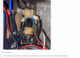
It’s a bit tricky to photograph the terminals of the batteries because access sucks. I can’t be bothered to pull them out of their locations but I know that there is only one cable coming from each terminal with all cables being the same length:

One + from each to a bus.
One - from each to the battery side of the shunt.

I’m 100% confident that all is correct although there are too many connections to the shunt, as could do with a separate bus to tidy things up which I will do when the weather sucks and I’m not wanting to make more entertaining use of my time time.

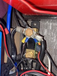
I am aware that the below photo shows the inverter negative connection to the shunt with too much exposed cable core!

1627507109007.jpeg

Don’t judge me!

The two cables (towards the bottom of the photo) are the the battery side of the shunt which are obviously to each battery!
 
Last edited:
ah, that may it . .


This is correctly reported on the VRM but what is missing from the VRM is the amount of power that the Ecoflow consumes once the solar is in full flow but the main batteries are in float.


the shunt will only monitor current flow in or out the battery bank.

when the battery is 100% and you have full solar the the power is being developed by the panels and being consumed by the Eco flow directly - so completely bypassing the battery shunt (which is correct and how it should work)

you can use the MPPT monitor to see the 8A going into the ECO flow. (as 8A coming from the MPPT, but seeing 0A on the shunt as battery full = 8A going to ecoflow via LOAD OP)


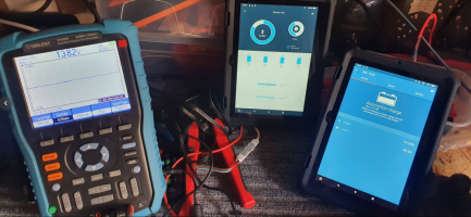
what i do is run two tablets (as an example)

One showing the battery shunt - so power in/out the battery.

and

One on the MPPT showing power developed from the solar.

with those two i can see where the power is going. ie - battery or to loads.


example:


1627545818605.png


a bad example as those tablets are show a victron charger and a Poweroad battery APP.

but you get the idea.
 
looks ok and functional to me.

maybe in future you could look at fitting a nice fat NEG busbar at some point?

possibly move the small gauge cable rings to the top, to give the large terminal rings max metal to metal contact? . . . but thats just being super picky.


1627546079378.png
 
easy way to check over the system is to throw a blanket or two over the solar panels to cut out the solar incoming power. (or just do it at night time)

then start testing the loads and make sure they are all registered on the shunt.

if they are then the cabling is correct.

as we see above current flow from the MPPT will bypass the battery shunt and offset that power reading when the sun is out. - normal.

you could fit a secondary (stand alone) power meter if you really wanted to?

either on the ECOFLOW feed or MPPT output?


i remember a member on here having some funny reading on his Victron setup . . . using MPPT,charger.shunt etc etc on VE Direct.

His fix was to delete all the VE networks stored in all the devices . . . . . . . .

the create a new VE network from scratch . . . starting at the shunt i think . . . then adding all other devices to that network.


.


1627546593903.png
 
Thanks for your comments. The big fat bus will get chucked in when there is no sailing, camping, canoeing, paddle boarding, cycling or any other things to do!
By the time that happens it will be September and @BognorMotors will have sorted my new vehicles, which will also give me many things to do which are more fun than fitting a neg bus, but it is on my list as I do need to do a proper job!
I am currently sat somewhere near Norfolk called Magpie Meadow with nowt more than a tap and somewhere to pour the black waste..... ideal!!!
You are a star for helping people like me out on thus forum. I watch your posts with interest and am genuinely grateful for the time that you put in to help idiots like me!
 
Last edited:
Back
Top