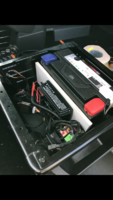
Victron Install

Gregga

Member
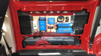
Finally got around to completing the installation of my comprehensive Victron electrical appliance install.

Very impressed with the bluetooth smart features of their kit that allow you to monitor the system. The MPPT has to be the stand out piece of kit from them.

The relatively slim appliances fit neatly within the panel of my T6 kombi
IMG_6565.PNG
 
Looks tidy so far.....

Are you powering the 240vac charger from the inverter?

I cant see any EHU feed yet.

Or solar inputs.


Keep the pics coming =]
 
Looks nice and tidy.
Can you mark-up each item to say what it is and does?
Do you intend to insulate the van and how will the insulation not have an adverse effect with those electrical bits?
 
Looks nice and tidy.
Can you mark-up each item to say what it is and does?
Do you intend to insulate the van and how will the insulation not have an adverse effect with those electrical bits?

Still work in progress for now. Setup consists of (From left to Right):
240V consumer unit for Electric Hook up (under bonnet hookup fed to consumer unit). This is directly connected to a Victron Blue Smart Charger 12V/30A to fast charge the system.
Victron Smart SOLAR MPPT *75/15 - Solar controller with monitored load output to the leisure circuit fuse box. This allows me to monitor all the current draw from my leisure circuit
Victron Phoenix Inverter 12/375 Pure Sinewave & VE Direct Bluetooth dongle. For powering 240V appliances upto 400W

I also have a few Victron VE battery sense monitors mounted to the starter battery and leisure battery (under drivers seat). These allow for a bluetooth network to be setup allowing for the MPPT to optimise solar charging by eliminating electrical losses within the circuit and battery temperature. This is because the VE battery sense is directly mounted to the battery where as the MPPT is hidden some way away from my leisure battery.

Lots of videos of the victron kit on youtube

IMG_7481.PNG
 
Last edited:
Still work in progress for now. Setup consists of (From left to Right):
240V consumer unit for Electric Hook up (under bonnet hookup fed to consumer unit). This is directly connected to a Victron Blue Smart Charger 12V/30A to fast charge the system.
Victron Smart SOLAR MPPT 100/20 - Solar controller with monitored load output to the leisure circuit fuse box. This allows me to monitor all the current draw from my leisure circuit
Victron Phoenix Inverter 12/375 Pure Sinewave & VE Direct Bluetooth dongle. For powering 240V appliances upto 400W

I also have a few Victron VE battery sense monitors mounted to the starter battery and leisure battery (under drivers seat). These allow for a bluetooth network to be setup allowing for the MPPT to optimise solar charging by eliminating electrical losses within the circuit and battery temperature. This is because the VE battery sense is directly mounted to the battery where as the MPPT is hidden some way away from my leisure battery.

Lots of videos of the victron kit on youtube

View attachment 57234
Interesting. I have almost exactly the same kit as you, though mounted under the driver’s seat, but you seem to be using it differently. Are you saying that you are ONLY using the load output on the 100/20 ie it is feeding your leisure battery so that you can monitor all the current drawn? I thought this output was just a direct feed without battery charging sensing to feed things direct, bypassing the battery, so I only use it to supply a low current trickle charger for the starter battery. If I’ve understood your setup correctly then I’d like to do the same, I like the idea of being able to monitor the total current drawn.

Edit; just noticed that the solar controller in the photo is the 75/15 rather than the 100/20 so presumably this was an earlier iteration of your setup, but it looks as if the battery charging output and load output are both connected. I’m confused now.

oops, your right im using a 75/15 MPPT!

My Leisure battery is connected to the +- of the MPPT and I am using this to monitor my leisure circuit.
I am using the load output for my low current drawing appliances within my leisure circuit (LEDs, fridge, tap etc). None of which exceed the maximum 15A output rating of the 75/15A controller when being used simultaneously. This allows me to monitor the current draw of these appliances. Once my solar is connected up I can monitor the current input of the panels too..

My Diesel heater and Inverter (high current draw) are not connected to the load output of the MPPT and are directly connected to the battery. However i can monitor the power output of the inverter via the victron app to get some idea of draw..

You can also isolate the load output via the app with the victron MPPT allowing you to completely turn off the leisure circuit when the van is not in use.
 
Last edited:
oops, your right im using a 75/15 MPPT!

My Leisure battery is connected to the +- of the MPPT and I am using this to monitor my leisure circuit.
I am using the load output for my low current drawing appliances within my leisure circuit (LEDs, fridge, tap etc). None of which exceed the maximum 15A output rating of the 75/15A controller when being used simultaneously.

My Diesel heater and Inverter (high current draw) are not connected to the load output of the MPPT and are directly connected to the battery. However i can monitor the power output of the inverter via the victron app to get some idea of draw..

You can also isolate the load output via the app with the victron MPPT allowing you to completely turn off the leisure circuit when the van is not in use.
Ah, you are using it the same as me then. How are you getting a read out of the current drawn on the leisure circuit though, on the Victron app I can only get a readout of current drawn from the Load output, the battery connection only shows what is going into charging the battery. What am I missing?
I started with a 75/10 but the 10A connection was proving a bottleneck with my 250W panel. The 75/15 would probably have been fine but I decided to jump 2 steps and get the 100/20 to allow for future expansion (which I now realise I won’t need :rolleyes:)

perhaps a schematic from my old van my help explain? Its similar to my setup now in the T6

Note - unlike my schematic, to get an accurate load output reading the negative terminal must also be directly connected to the negative of the appliances. Don't connect the negative load output to the chassis earth if you want accurate measurements.
 

Attachments

  • GJ15 EYB Wiring Schematic Rev A.pdf
    385 KB · Views: 64
No dc-dc or b2b charger then?

Yes - CTEK 250 under passenger seat. Unfortunately I brought this before Victron released the Orion B2B charger - again with bluetooth app

*edit - the wiring schematic was from my old T5 which didnt require the B2B (although B2B are far superior to split charge relays!)
 
perhaps a schematic from my old van my help explain? Its similar to my setup now in the T6

Note - unlike my schematic, to get an accurate load output reading the negative terminal must also be directly connected to the negative of the appliances. Don't connect the negative load output to the chassis earth if you want accurate measurements.
So you are running everything from the Load output and only using the main output to charge the leisure battery. I'm familiar with how to measure current from that with the app, but I thought the load output only worked while it was getting external charge? Does this mean I could shift my entire leisure circuit onto the Load output of the MPPT and it will still get power back from the battery when there was no solar or EHU available? Sorry for being thick but if this is the case I want to do this, it seems much better.
 
So you are running everything from the Load output and only using the main output to charge the leisure battery. I'm familiar with how to measure current from that with the app, but I thought the load output only worked while it was getting external charge? Does this mean I could shift my entire leisure circuit onto the Load output of the MPPT and it will still get power back from the battery when there was no solar or EHU available? Sorry for being thick but if this is the case I want to do this, it seems much better.

In short - Yes!
 
Back
Top