How I think I'm going to do it!

Samro

Senior Member
VIP Member
T6 Legend
After reading loads of amazingly informative threads on this forum, I thought I'd start my own thread. (Largely inspired by @Dellmassive 's really blooming useful and informative "How I done It!" thread.)

Basically, I haven't "done it" and simply intend on "doing it"!

I thought it would be good to have a thread on this forum that can be used as a sounding board before I get things totally wrong!!

The reason for this post is that I have a new vehicle on order which I am going to be using as a "Demonstrator" for some kit that my company sells and installs in the marine leisure industry. It turns out that there are loads of differences between boats and vans!.........Smart alternators, 12 volts (Who thought that was better than 24V!), massive conducting body shell, etc.

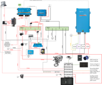
I thought I'd kick off my thread with a diagram of how i intend on "Doing it”.

Not too sure why I’m questioning this but I’m not sure about the use of a smart shunt when all the negs are running off to the chassis. I have simply taken the shunt to ground and then also grounded the main neg bus to the chassis and I am confident that this is right, but boats don't have a convenient metal body to use as a gigantic bus bar. Can I check that this is the correct thing to do with one of the "Gurus" on here?

Notes that help explain oddities in my schematic:
A. The water heater is to only run on twelve volts (from the leisure battery) when the following criteria is met:

1. Engine is running and leisure battery is charging through DC DC charger.
2. More than 10% of water in FW tank.
3. Leisure battery is more than 50% charged (Or whatever other percentage is chosen after install.)

Or

Solar input exceeds 20A and battery charge is greater than 70% (or whatever other percentage is chosen after install.)


B. There is an isolated regulated 12v supply for sensitive electronics and also to stop regular faffing around with fuse of the Wallas hob when the voltage falls slightly under 12.6volts. (Couldn’t Wallas fit a voltage stabiliser theirselves to improve the reliability of their otherwise excellent kit?)

The rest seems pretty self explanatory, but if anyone has any better ideas or any suggested changes I'd love to know?

I would rather know that I have a poor design now than after installing all of the kit, so hoping I may get some constructive feedback:
1616043801812.png

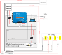
The front end of the installation, including 400W of solar and DC-DC Charger and Lithium battery under the drivers seat. Note the Smart Shunt being taken straight to the body of the vehicle. This is the bit that is alien to me!
1616043670034.png
 

Attachments

  • (Front) LWB Schem 17.3.21.pdf
    1.6 MB · Views: 8
  • LWB Schem 17.3.21.pdf
    1.7 MB · Views: 10
Last edited by a moderator:
I’m confused why you think you need to run negatives to the chassis? You can do this if you want but it’s good practise to treat it like a boat and cable negatives back to the battery

I like the idea of using the Cerbo relay to permit the 12V water heater to run, that’s really smart. Why do you need engine to be running though, can your lithiums not provide the load you need? Or do you intend to leave water heater on permanently and treat it like a calorifier so it only heats up while driving?

You haven’t got a cable for the Multiplus trickle charge to starter. I’d also suggest a higher power DCDC charger if you’re going to be running a water heater while driving.

Looks really good in general though and some clever ideas. Always like seeing how boat builders put together their electrics
Cable for trickle charge of the starter bat? I have a Multiplus “Compact” and I understood that Victron have removed the second feed to the starter batt since ”compacting“ the multiplus. Am I missing something?

Would you still ground the shunt to the chassis and run cables in addition, or ditch all of the grounds in their entirety? (IE: Keep it familiar like a boat,)

The engine would need to be running to prevent flat leisure battery. A constant 25A draw is too much unless some sort of management is implemented.

I had a play today with a Venus GX and controlling the relay didnt go as smoothly as I wanted! I wanted to add to my schematic with the Cerbo triggering the relay when the MPPT input a certain current.... it went pear shaped as the alarm functions, but I’ll be dammed if I can get it to switch the relay in the same way as it does when triggering the relay from “battery capacity”. I’ve asked Victron for support on this.
 
Sorry I meant to say... this is a demo vehicle for my work so I need to explain. (Albeit a useful toy as well)

Boats using outboards are getting bigger and these boats can’t use a conventional calorifier (with engine coolant providing the hot water.) Lots of these boats have roof space for solar. Hence the design.
 
I didn't realise the compact doesn't have the trickle charge... we never use them as the new model Multipluses (500Va up to 1600VA) are a lot cheaper. The only advantage I can see of the compact is the second AC-out but it doesn't look like you're using this anyway? Unless I'm missing something and there is another reason to use the Compact, then go with the new model and get the trickle charger (and save £200!).

You still want to use the chassis as a common ground with the vehicle electrics but you only need to connect from the inverter and the shunt (I usually do it from negative busbar as its easier). I just meant not to use the chassis as a conductor for your 12V circuits - better to have a Blue Sea fuseboard with a negative busbar and run twin core cables from this to each 12V appliance. I guess that's what you're used to anyway?

Interested to see how you get on with the Cerbo. I've only just started playing with Cerbo relays, managed to get it to shut off a pump when water tank runs dry but that's it.

I've attached one of our schematics which might give you some ideas (we create these free for customers when we supply battery and Victron kit). Note the ground connections at inverter and busbar only.
 

Attachments

  • Roamer System Schematic.pdf
    955.3 KB · Views: 41
Thank you. I've reverted back to running cables in a conventional fashion!

Your schematic looked straight forward with its single battery bank.

My install is is messing with my head............. with the mixture of a lithium and an AGM battery.

I was of the opinion that the starter battery stays out use, keeping itself ready to do its job of "starting".

That said, it would be good for the starter to receive any excess charge from the solar just to keep it "floating". I toyed with shoving in an "Argo Fet battery isolator" to manage any excess solar which will be just wasted once the leisure battery is full. However, I thought about the consequences of this and I quickly achieved brain ache. In my head things got waaay too complex waaay too quickly! Namely:

1. Not being able to work out how to deal with the Smart Shunt! What will happen as the MPPT is incorporated into the VE network and therefore the Cerbo sees the MPPT's solar input, only to then fail to recognise that this input is given away to the engine start battery when it fails to see charge at the shunt? The Argo Fet seems like a fairly basic bit of kit (like a less inefficient split charging diode) and whilst I can see that it will do what I want I’m sure it will royally jigger up the battery monitoring?

2. The MPPT controller will operate according to the parameters set by the user. If the battery pre-set is set to suit a lithium setup, then using a Argo Fet to top up the AGM starter battery a little, but not properly because it is being charged as a lithium which is not cool and ................ooooh is lockdown nearly over? There will be beer in pubs and i will soon have a camper van, my boat will be launched and the weather, check it out............ it is daylight until 6.... yes 6!

How concerned should I be that the starter battery will deplete? I can’t see why it would, but I’m a novice with “van plans” and welcome your views?

I've amended my design to ground the main bus and the inverter. I'll have a look at the kit i have assigned for this and see if I'm missing something on the trickle charge front.

I would love some views on if there is a way to retain the excess solar which doesn’t lead brain fail!
 
Last edited:
ah man you must’ve been dreaming about batteries :slow rofl:

Unless this is your daily runabout then you DO need to think about keeping the starter topped up, leaving it sat on the drive for a month or two will kill the battery.

Dont bother with diodes. Just get a new model Multiplus which is cheaper and will trickle charge. Or even better, if you want to simplify the install then get an Easyplus… it’s a Multiplus with MCBs built in. It even gives you the AC-out2 back.

If you really like spending money for the sake of it though, Sterling do a battery maintainer you can use.

Think of the shunt as the doorman at a nightclub (remember those? Haha). All it does it count heads in and out to tell you how many people are inside. It then displays the head count on the Touch GX. The Cerbo itself isn't doing any counting. So it doesn’t matter if your solar charges your starter, or you take a bit from the leisure battery to the starter. It’s like the doorman turning people away when they’re full and they go to the club next door instead. The shunt is your last point on the circuit so everything in or out has to pass through it and as long as you don’t leave any back doors open (like connecting a circuit negative directly to the battery) then the SoC of your leisure battery will be accurate.
 
Last edited:
I’m confused why you think you need to run negatives to the chassis? You can do this if you want but it’s good practise to treat it like a boat and cable negatives back to the battery

Could you explain your thought processes on this. From the research I have done I would say its the opposite. Basically, why run a wire when there is a path already there?
 
Could you explain your thought processes on this. From the research I have done I would say its the opposite. Basically, why run a wire when there is a path already there?

It's personal preference and both ways work. Cabling negatives back to the fusebox is good practise because it makes fault finding a lot easier, if you have a bad earth then you have everything in one place. Using the chassis as a giant busbar means multiple connections and therefore multiple points of failure, you also need to make them accessible which isn't always practical in a converted van.

Twin core flatwall cable is cheap and easy to run around the van, and a blade fuse board with negative busbar is only slightly more than a standard one so there is no real downside to cabling back to the fusebox except maybe spending a few quid more on cable.

It's still important to have a common ground however, this is why you connect to the chassis at the battery - it's just that you're doing it with one thick cable instead of dozens of small ones.
I wasn't meaning dozens of small connections. I really meant a connection from the starter -ve to the chassis and one at the leisure battery location. So basically not running a large cable from battery to battery negatives. Some MPPT controllers and non-isolated and must use the chassis.
 
Ok yep, you're talking about a common ground - we do this from the main busbar. See pic below. Original comment was about the individual 12V circuits, lights, USBs etc. You can connect negatives of these to chassis too but we run then back to the blade fuse holder instead.

fuse and busbar.JPG
 
ah man you must’ve been dreaming about batteries :slow rofl:

Unless this is your daily runabout then you DO need to think about keeping the starter topped up, leaving it sat on the drive for a month or two will kill the battery.

Dont bother with diodes. Just get a new model Multiplus which is cheaper and will trickle charge. Or even better, if you want to simplify the install then get an Easyplus… it’s a Multiplus with MCBs built in. It even gives you the AC-out2 back.

If you really like spending money for the sake of it though, Sterling do a battery maintainer you can use.

Think of the shunt as the doorman at a nightclub (remember those? Haha). All it does it count heads in and out to tell you how many people are inside. It then displays the head count on the Touch GX. The Cerbo itself isn't doing any counting. So it doesn’t matter if your solar charges your starter, or you take a bit from the leisure battery to the starter. It’s like the doorman turning people away when they’re full and they go to the club next door instead. The shunt is your last point on the circuit so everything in or out has to pass through it and as long as you don’t leave any back doors open (like connecting a circuit negative directly to the battery) then the SoC of your leisure battery will be accurate.
I understand the shunt functionality, however what I didn't get is how the info would look on the VRM in the following situation:

1. Shunt is seeing no charge/discharge.
2. MPPT is reporting charging current to the battery to the VRM.

It would all become a mess and that's why I canned that idea quite early on!

If you look at your stock Multiplus units, I bet you'll find that the trickle feed connections no longer exists. I've just checked a stock 12/1200/50 unit and it doesn't have them. (They defo used to!)

The vehicle will be a daily drive and I may shove in a separate charger for the starter as this will provide redundancy, which may work for this application.

That's weird, we've sold quite a few this month and they all have a trickle charger. Just checked manuals for both new Multi and the compact and both state its there. Where are you looking for it? Not sure on the compact but on the new Multiplus its just a spade connector underneath, it's not obvious though.

The only info about battery state of charge comes from the shunt. The MPPT might be telling the GX that you've got 20A coming in from solar but unless this passes through the shunt then the SoC on your Touch GX will not change.
 
It isn't weird.................. I am stupid! I just asked one of my engineers and showed him a stock Multi and he simply told me that I couldn't be trusted with Duplo! Why are engineers so rude?

I had to tolerate the " You cant be trusted to install anything", "Get back in the office", "Your van is going to burn", etc!

I feel kind of stupid, but who on earth expected to see a single recessed spade as a "Starter Battery Plus", hidden in there!

How embarrassing!

Haha no worries! You had me doubting myself for a minute there though :slow rofl:
 
Ok yep, you're talking about a common ground - we do this from the main busbar. See pic below. Original comment was about the individual 12V circuits, lights, USBs etc. You can connect negatives of these to chassis too but we run then back to the blade fuse holder instead.

View attachment 108911
Yes, Im building mine in a box until its all worked out and tested in the van. Then I will decide if I can squeeze it all under one seat. o_OCBAA5383-0A40-4C04-87A6-FE1F5E75DF01_1_105_c.jpeg
 
I've not got much "squeezing under seats" to worry about on this one because the idea is that a false back will be installed on the rear of the cupboards when the converters do their thing. The plan is that when the driver side sliding door is opened, this will reveal all of the kit all neatly laid out. That's the plan anyway, but the logistics behind the whole thing are a bit of a nightmare, not least in obtaining the vehicle from VW in the first place!

I am also waiting on a second van for work. This will largely be used as a mobile office (largely for offsite diagnostics), but also a quiet space to escape my open plan office to work without constant interruption, Some load carrying will be required, but it certainly wont be properly loaded and contaminated with no end of yucky stuff like our other vehicles!

Due to the requirement to charge mobile tools, run diagnostics kit, etc there is a fair amount of electrical kit going into this vehicle. I initially gave the converters a list of the required kit and told them i wanted it under the seats and they looked at me like I was taking the pi*"!

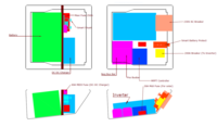
I drew up a scale drawing of all the kit that I want to fit under my seats after finding a CAD drawing of the seat base on this forum. I think that the converters still seem to think I am a bit mad but they don't know what we have squeezed into some spaces in the marine leisure world!

So still not sure if it will all work out as I am still waiting on build dates, let alone delivery dates for the vehicles! I'm getting worried that if much more time passes VW will have to deliver a milk float!

I have ditched the 230AC breaker box and gone with a proper distribution box which will be mounted in the back of the van. (Our certified sparky called me "A f***ing liability" when I showed him what I originally specced!.... Like I mentioned to Steve at @RoamerBatteries , Engineers are so rude!)
1616167909941.png

The full kit (Apart from the 150W solar panel on roof)
1616169956780.png
 
Last edited:
I've not got much "squeezing under seats" to worry about on this one because the idea is that a false back will be installed on the rear of the cupboards when the converters do their thing. The plan is that when the driver side sliding door is opened, this will reveal all of the kit all neatly laid out. That's the plan anyway, but the logistics behind the whole thing are a bit of a nightmare, not least in obtaining the vehicle from VW in the first place!

I am also waiting on a second van for work. This will largely be used as a mobile office (largely for offsite diagnostics), but also a quiet space to escape my open plan office to work without constant interruption, Some load carrying will be required, but it certainly wont be properly loaded and contaminated with no end of yucky stuff like our other vehicles!

Due to the requirement to charge mobile tools, run diagnostics kit, etc there is a fair amount of electrical kit going into this vehicle. I initially gave the converters a list of the required kit and told them i wanted it under the seats and they looked at me like I was taking the pi*"!

I drew up a scale drawing of all the kit that I want to fit under my seats after finding a CAD drawing of the seat base on this forum. I think that the converters still seem to think I am a bit mad but they don't know what we have squeezed into some spaces in the marine leisure world!

So still not sure if it will all work out as I am still waiting on build dates, let alone delivery dates for the vehicles! I'm getting worried that if much more time passes VW will have to deliver a milk float!

I have ditched the 230AC breaker box and gone with a proper distribution box which will be mounted in the back of the van. (Our certified sparky called me "A f***ing liability" when I showed him what I originally specced!.... Like I mentioned to Steve at @RoamerBatteries , Engineers are so rude!)
View attachment 108974

The full kit (Apart from the 150W solar panel on roof)
View attachment 108983
Nice. Would defo recommend checking out Roamer Batteries vs TN Power though
 
Nice. Would defo recommend checking out Roamer Batteries vs TN Power though
Trouble is the TN110 measures L355 x W176 x H189mm which I reckon is a just a good under seat fit. (I could be wrong as I’m basing this on CAD drawings)
 
Back
Top