Who can help me understand my 12v install

timthetinyhorse

Senior Member
VIP Member
T6 Guru
Hi All,

Firstly for all of the help people have me when asking about leisure battery installs and what I need to do/purchase. I got some great advice from the likes of @Dellmassive and that’s what makes this forum the great place it is! I ended up buying a DC-DC Vitron Orion kit from Rayne Automotive and now trying to find time to wire the whole thing up and install the battery.

Next steps are working out how I go about completing the 12v install on the van.

The DC-DC kit came with fully finished cables and a 6 way fuse box and this is where my questions begin…….firstly people talk about an isolator after the battery. I assume this should be installed before the fuse box?

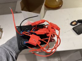
To keep things neat and simple I have also ordered on of the below control panels as in pics below. 5 switches, one 12v style lighter socket and two USB.
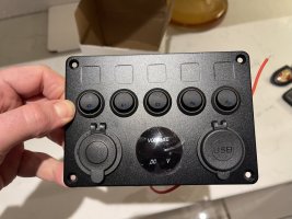
IMG_8411.jpegIMG_8412.jpegIMG_8413.jpeg

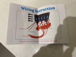
As can be seen this panel appears to have a single live feed from fuse board and then a single earth back down to earth. The switches then have fuses in the positive and I assume I then take back to earth after components.

So firstly should I use the single feed from fuse box to this unit or split them to individual feeds from fuse box?

In my lighting circuit should 12v led lights be wired in parallel or series?

I plan on running in wires so the van is prepped for heater and water when/if I decide to install. Will this dictate the answer to the single feed from fuse board?

Sorry for so many questions here just want to make sure I do a good job of this install
 
That switch panel...

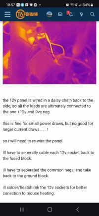
The black 0v is just for the switch LEDs. So a single link to 0v will be fine.

As for the single +12v supply id split that into twos and run them from your fuse box..... That as a single will get hot, I did on mine..... Somi split them up.


More info on the battery box build.


...


..


Screenshot_20240118_185734_Chrome.jpg
 
Thanks for that, was my exact concern with the small 12+ feed wire. Slowly learning my way back into electrical here! Over 10 years since I was working on industrial circuits and clearly the knowledge drop has been vast
 
I can’t really see from the photos if one of the switches turns the voltage meter on and off but if not you should do that, having the voltage meter on all the time will not only be a permanent draw on the leisure battery but more importantly your van will feel like Blackpool seafront at night when you’re trying to sleep, it’s amazing how bright those meter readings can be in the dark
 
Hi All,

Thanks for the help so far.

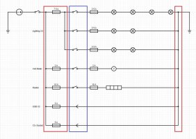
I have knocked up this quick drawing to help myseflf undertsnad what i need to do. Red box represents the fuse box and earth bus and the blue are the control pannel components.

Does this look phesable and are my fuse values sufficient? Lamps are 12v 3W Puck style LED, The two USB ports are 2.1A.

Cheers

diagram.JPG
 
You don't need a fuse before and after the switch for the volt meter and heater. I wouldn't put the heater through those switches, they're not big enough.

You need a fuse closer to the battery to protect the cable from the battery to your switch panel
 
Couple of thoughts

You probably don't need to fuse both sides of the switch for the voltmeter and heater. It's potentially a good idea on the lights though as a fault on one circuit should blow the low fuse first and not cut out all the lights.

If the round device is your battery then you need a large master fuse as close to it as possible to protect the wiring run.

Is the switch before the red box a master cut off? If not your USB sockets are on all the time which may be a parasitic drain.

Are the switches in the panel rated for 15A? The heater circuit stands out as a load. What type of heater is it? You may be better considering a dedicated high current switch for the heater and using that panel switch for the USB.
Wot he said :cry:
 
Thanks for all of the advice so far guys really appreciate it.

have made some comments below.

in terms of my fuse ratings would you say they are correct?

You don't need a fuse before and after the switch for the volt meter and heater. I wouldn't put the heater through those switches, they're not big enough.

You need a fuse closer to the battery to protect the cable from the battery to your switch panel

Ok fair enough so take the heater feed straight from the fuse board?

DC-DC charge kit was supplied with a 6 way fuse board but no inline fuse from the battery to the fuse board so assuming I need an inline fuse there, what size would you be looking for there?

Couple of thoughts

You probably don't need to fuse both sides of the switch for the voltmeter and heater. It's potentially a good idea on the lights though as a fault on one circuit should blow the low fuse first and not cut out all the lights.

If the round device is your battery then you need a large master fuse as close to it as possible to protect the wiring run.

Is the switch before the red box a master cut off? If not your USB sockets are on all the time which may be a parasitic drain.

Are the switches in the panel rated for 15A? The heater circuit stands out as a load. What type of heater is it? You may be better considering a dedicated high current switch for the heater and using that panel switch for the USB.

yes so round device is battery (had limited options in the software) and the switch after is the master cutoff (Still trying to find one that works as the current one I have the pins are too big for the supplied cable and ring terminations)

only reason I have a fuse either side of the switches as the panel will be fed from the 6 way fuse board and the panel has come supplied with inline fuse holders so thought why not make use of them. So the 7.5A fuse would be on the fuse board and then the 2.5A inline after the switch.

ok makes sense on the USB, I will swap that out for the heater so its switched, heater was future proofing as I don’t have one yet but wanted to put the feed in. Suppose really the volt meter could also be on that feed.
 
Ok fair enough so take the heater feed straight from the fuse board?

DC-DC charge kit was supplied with a 6 way fuse board but no inline fuse from the battery to the fuse board so assuming I need an inline fuse there, what size would you be looking for there?
The fuse rating all depends upon the thickness of the cable
 
Back
Top